Showing posts with label QRSS. Show all posts

Thursday, March 21, 2013

RPi as a WSPR Beacon with PA47


UPDATE:
Sorry,  this did NOT work as expected, the Wsprrypi code is still being developed. The second fork of the program is available. The RF output of the of the RPi is less noisy if the DC supply is from a well filtered source.


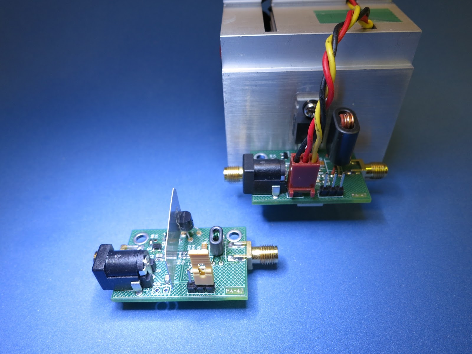
I have previously built my Homebrew PA47 Power Amplifier for a Propeller Microprocessor Beacons (see previous selected posts). The Propeller provides 12mW to drive the PA.

The Raspberry Pi provides about the same output power via the Dan Ankers Wsprrypi program. Therefore. it was a simple mater of connecting to the correct pins on the RPi GPIO Connector to give it a try. Thanks Dan !

Here is my initial lash up, with just a Low Pass Filter (LPF).
RPi WSPR Beacon with LPF
Measure Output into 50 Ohms =  5dbm
Here is the RPi and the PA47, with input and output LPFs attached.

With the two low pass filters, the measured output is 9.4 V PP at a 50 ohm load, or 220mW, which is 23.4dbm. The Dan's WSPR program uses only about 3% of the CPU.


I have plans to modify Dan's Wsprrypi program to include other beacon modes (e.g., QRSS) similar to those that I have used with the Propeller Processor.

FYI, This my complete family of experimental PA47 Amplifiers.
My PA47 Family
Max Power - 1w, 5w and 15w

On the air, WSPR Received Reports will be added here.


-- Home Page: https://WA0UWH.blogspot.com

Thursday, February 28, 2013

Rpi on the Network

As mentioned in the previous post, I now have my Raspberry PI (Rpi) connected to the Network, serving Web Pages and providing (my) access via SSH and Remote Desktop.

Only one wire is needed for this configuration, that is the 5 Volt power from a 1 Amp wall wart. Network access is via the USB WiFi Adapter as shown in the photo. This Rpi can be accessed from anywhere in the world as http://Rpi.WA0UWH.com:8040 . Currently it is serving only a single web page, other fun pages (or links) will be added later.
Rpi running a Web Server, SSH, and Remote Desktop
http://Rpi.WA0UWH.com:8040
My plans include connecting the Rpi to an Ensemble Receiver (SDR), which can be done with only the addition of an Antenna and USB Sound Card.

I am considering moving the Rpi and the SDR to a remote location (where I have WiFi access) so that I can Transmit from my Shack, without overloading the SDR. This remote location will be good for remote QRSS Grabber operation.

I am impressed with the Rpi, it is a fun system.


-

Thursday, January 31, 2013

PA47 Now Ready for On The Air Tests

Thus far I have NOT connected my PA47 Amplifier to an antenna, because I was not sure of it output harmonic content (see previous posts).

Last night at our monthly P&C group meeting, Wayne - NB6M presented a demonstration of his new DSA815 Rigol Spectrum Analyzer with one of his oscillators and the effects of a output filter devices. His filter completely eliminated (down into the noise floor) any harmonic content.

As a second example and demonstration, I provided the PA47 Amplifier and a LowPass filter. A 50 Ohm load and 40db tap was used to reduce the input to the Analyzer. Actually, both the 1 Watt and the 15 Watt versions of the PA47 were checked, the results were about the same.
The 1 Watt and 15 Watt Version of PA47
The output filter that I used, is a simple Chebyshev 5 Pole Filter (as previously posted).

30m LowPass Filter as Designed with LtSpice
The filter was originally designed via an Online Filter Design program, and then available multiple 330pF 1206 SMD caps were used to obtain the nearest values, 3 caps for each end, and 4 for the center. The cores were wound as necessary by measuring the results on an AADE LC meter.

30m LowPass Filter as Implemented
The Results

Wayne declared the PA47 fit for Amateur Radio Service. The second harmonic was down 51db and the third was down 67db from the fundamental.
PA47 Connected to
DSA815 Rigol Spectrum Analyzer
I will soon connect the 1 Watt version of the PA47 to an Antenna, and use if for QRSS Beacon Service on 10.140050MHz (+-50).

--

Wednesday, March 21, 2012

My 30m QRSS Grabber is Back Online

Finally, my 30m QRSS Grabber is back online. It has been off for about three years, lacking the bits and pieces that make it all work easily (and maybe my lack of trying :-(

My QRSS Grabber URL is at:


A link to the Grabber is provided on the right of my blog.

If you do not know what QRSS is all about, check out:

and 

Several things all had to come together for me to attempt to re-establish my Web 30m QRSS Grabber.
  • I recently learned; for a donation QSL.NET is providing web space to Amateurs for Ham Radio related topics (this may be old news to some, but not to me).
  • A new ARGO program is being beta tested and copies available for use. A new capability included an FTP client for capture transfer to a server.  A beta copy can be downloaded from here.
Establishing an online QRSS Grabber has never been easier.
  1. Establish an QSL.NET Web and FTP account (takes a few days)
  2. Build a few simple web pages
  3. Run ARGO, schedule a grab and transfer to your QSL.NET account
  4. Publish your web page, Let the QRSS Compendium Owner know your URL, GRID and capt file name.
  5. Set back and watch the fun
Note: I understand that with a little more difficulty, a Grabber can be established using the Spectrum Lab Program ( I just have not yet found all of the needed magic).

So, now anytime I am not activity Transmitting, I will be providing a Northwest QRSS Capture Service for the MEPT QRSS Knights.

Join the QRSS Knights, and have some fun, if you have spare receiver time available.

( Hopefully, this time my grabber will be up more, than down ;-)


UPDATE
Jeff - KO7M took up the challenge, and has put up his own KO7M Grabber, the more the better.


UPDATE

Due to the new Beta ARGO getting lost while attempting to transfer grabs to QSL.NET my QRSS Grabber is DOWN, again! More investigations is needed to proceed. While testing, the Grabber will be up, but mostly down.

--

Friday, March 16, 2012

Measured Success

After installing the Homebrew PCB with the 10MHz TCVCXO Frequency Standard Clock on the Propeller, I finally got it connected to an Antenna as a WSPR, QRSS and OPERA 200mW Beacon.

The results are amazing, the Frequency is measure as very Stable and the Frequency is measured to be as set.  The reporting site, and measurement that I trust the most is W1BW (Operated from ARRL HQ);  they report Zero Hertz Drift and at the desired frequency of 10.140210MHz - exactly as I have programmed the Beacon.

Note: Not only does the TCVCXO provide for a stable and accurate RF frequency, but it also provide accurate scheduling for the Beacons. WSPR requires scheduled transmittion on two minute boundaries, starting the actual beacon two seconds (+/-1) past the minute. This Propeller Beacon is on-time, every time :-).

Also, the three beacons run in quick succession, that is: WSPR starts on a two minute boundry (runs for 2 min), followed by QRSS on the top of the next minute (runs for about 3 min), followed by OPERA on the next minute (runs for about 2.2 min). Then all repeats 10 minutes later. The 10 minute schedule allows the QRSS beacon to be displayed at the same place within the 10 minute remote Grabber captures.

I am receiving many reports (spots) from around the US, no DX yet, but the night is young.
My WSPR on the Map
Note: the W1BW report (at 3939 km) in the following list (click to view).
My WSPR Spots - as Reported by WSPRNET.org
Also, the following was reported by the KK7CC Grabber, note the frequency scale, which is out side of the normal QRSS Subband, I had to pick a frequency to allow my signal to show up on his Grabber. I picked 10.139930MHz, KK7CC reports the same !

My signal is the lower trace with Propeller graphic and my Call in slash code.

My QRSS on KK7CC Grabber - Las Vegas

I am a Very Happy Camper !!   :-)


UPDATE
New DX report at 7049km with only 200mW:

TimestampCallMHzSNRDriftGridPwrReporterRGridkmaz
 2012-03-17 03:54  WA0UWH  10.140204  -24  -1  CN88xc  0.2  WA2YUN  RK39hh  7049  270

And, Two more:

TimestampCallMHzSNRDriftGridPwrReporterRGridkmaz
2012-03-17 10:04  WA0UWH  10.140208  -14  0  CN88xc  0.2  VKFRG  QF44np  12766  244 
 2012-03-17 10:04  WA0UWH  10.140199  -26  0  CN88xc  0.2  VK4TMH  QG56fj  11758  252


--

Tuesday, March 6, 2012

A New Master Clock - Cont'd

Well, that didn't work as expected !

In an effort to thermally stabilize the output RF Frequency of the Propeller that I use for WSPR, QRSS, and OPERA Beacons, I attached a external 100MHz +/-50ppm/C Master Clock Chip in place of the vendor supplied 5MHz Crystal, see previous post.

The Propeller has options to multiply the supplied source as necessary to obtain the desired operating clock frequency. The supplied 5MHz crystal x 16 = 80MHz, for normal use. My external 100MHz oscillator is not multiplied and over-clocks the processor by 25%. It works and it is fast, but . . .

The 100MHz Clock is accurate for average Frequency, but it produces a lot of jitter. The jitter shows up in the output RF Frequency as noise. For a Beacon, which typically uses a band width of only a few Hertz, the jitter is unacceptable. The jitter appears as fuzz on the received signal.

Another Approach is Necessary

Another type of oscillator is the;  Temperature Compensated Crystal Oscillator (TCXO). The spec's on the TCXO's look very good. A high precision TCXO is typically +/-1ppm/C, with some parts rated as low as +/-0.5ppm/C. These parts are typically $5 to $10. But only a few limited frequencies are available, from 10MHz to 52MHz. They would work with Propeller but the internal PLL could not be configured to multiply the frequency. That is, the Prop internal PLL (1x, 2x, 4x, 8x, or 16x) could not be used, because the Prop PLL has an input limit of 4 to 8MHz.

So, I am looking for a low cost, high precision ~1ppm/C oscillator

  • 4 to 8MHz TCXO (to be used with Prop internal PLL)
  • Or, a 80MHz to 100MHz TCXO used un-multiplied in direct connection

Another type of oscillator is the; Oven Controlled Crystal Oscillators (OCXO), they are available with much better spec's (e.g, +/-0.005ppm), but they are very expensive (and large), > $150.


So far, a suitable part has NOT been found, . . . the search goes on :-)

Note: The included links are for Mouser, other vendors have a similar parts selection.

--

Monday, February 27, 2012

A True Software Defined Transmitter

The last few weeks; Julian - G4ILO, Jeff - KO7M and myself have been working on building WSPR, QRSS, and OPERA Beacons. For that, we have built everything around the Parallax Propeller Microprocessor. The processor, the protoboards, and associated peripherals (i.e, Rotary Encoder, LEDs) are generic and could be used for any microprocessor control project. Even the CW Key jack is generic and is connected to normal data lines, and therefore it could be used for other projects, such as, stereo audio output for a robotic sound system.

Stated another way, Nothing on the system could be considered Transmitter specific. This project is only a Transmitter because of the software that is running. Therefore it is a 100% Software Defined Transmitter, an "SDT".  I do not think there are many that can make the same claim.

A True 100%
Software Defined Transmitter
Only the optional add-on Output Low Pass Filter , Power Amplifier, and Antenna could be considered specific to a Transmitter. The raw processor provides about 7mW of RF power, the amplifier raises that to about 100mW. But contacts have been made with just the low power of the bare bones generic hardware as an SDT.

We have used the SDT as time scheduled WSPR, QRSS and OPERA Beacons and have successfully received reports from many places around world. With the addition of Jeff's Keyer Program, and my UI program (to take advantage of the LCD and Knobs) the SDT can be used interactively with a CW Key. As more software is developed, more modes and capability will be implemented.

The SDT In Action
Internet Based Map Report on the Left
Text Reports on the Right
The only new thing I plan to add to the collection of peripherals for the microprocessor protoboard is an external high precision master clock to help thermally stabilize the RF output frequency (parts are on order).

So far, I am very pleased with the results we have obtained.

NOTE: If you try this, make sure you use an output Low Pass Filter, as the Propeller output is a square wave with many harmonics. The FCC requires harmonics to be down by 43db.


If you are a HAM and interested, buy a Prop, join the fun.


(Note: I am not an agent or associated with Parallax)

--

Monday, February 20, 2012

Propeller Project Status - Update

Success, another major hurtle jumped for my multi-mode Prop (Propeller) Beacon GUI implementation. The Real Time Clock is working and providing scheduling for the Beacons.

As previously blogged, my goal was build (assemble) and configure the following (the current status shown):

UPDATE: I have updated the following to reflect current status. GUI is DONE  :-)
  • LCD Display
  •   - 100% DONE -

  • Audio Feedback (1/2 inch speaker, for beeps and squeaks)
  •   - 100% DONE - 

  • Real Time Clock
  •    - 100% DONE - and working! My WSPR Beacon is not ON schedule !! 
  •      The clock is spect'd at 5 ppm ( which is much better than the Prop ), I wished it had a 
  •      High Freq output port.

  • Two Rotary Encoders with Push Buttons
  •   - 100% DONE - Encoders and Buttons work very smooth and easy to use.

  • Several Generic LEDs (controlled via I2C)
  •   - 100% DONE - Two Red and two Blue, 0805 LED's mounted just below the Encoders

  • Maybe a Precision System Clock
  •   - 0% - I have some parts on order.

  • Provide native I2C control
  •   - 100% DONE - currently being used for control of RTC and I/O Expander to drive
  •     LED's,   more expanders can be added as necessary.

  • And, preserve at least 16 lines of direct I/O from the processor for add-on project control
  •   - 50% - Change of goal, only 8 data lines and I2C will be available for additions devices

UPDATE: A New Requirement

  • SD Card and File I/O
  • - 0% - Just Added


Due to Jeff's - KO7M programming efforts and his new Mores Keyer and Transmitter program,  I had to add two 3.5mm Jacks for a CW Key and Keyed Output Line, but actually, the ports are just data I/O lines available for what ever is needed. His Keyed / Transmitter is a fun little toy.

At this moment, I am watching the Display and Lights, while the Beacon runs WSPR, QRSS and OPERA in timed sequence (as necessary by WSPR). Next task is to hook it up the Low Pass Filter, the PA and the Antenna, . . . maybe soon.

This project has be a challenge, more due to my lack of knowledge or understanding of the Prop and the selected peripherals.

But, . . . It's all fun, with a Prop !!

-

Monday, February 6, 2012

Display ON

I have been running my 30m Propeller QRSS, WSPR and OPERA Beacon the last few days, and have received many local and DX spots as reported on the web.

A periodic restart (reboot) or re-program of the beacon is needed to keep the beacon on frequency, to change the mode, and set the right time sequence - which is a bit of a pain. What is needed is a GUI with display and controls to make adjustments as necessary while the beacon is running. To that end, I have been attempting to build a standard GUI for the Propeller Microprocessor - sounds simple doesn't it. Well it maybe simple after I get over some initial hurtles.

The first GUI hurtle was to get a LCD Display to work correctly, there are many contributed LCD driver in the Propeller Object Exchange Library, most use conflicting pin connection or they do not provide the 4bit data path that I desire for my display.

The GUI
The real problem here is there are Too Many LCD contributed drivers from which to choose. all with conflicting pin assignments and programming interface. It is difficult to understand the difference between them without actually downloading and trying each - which is very time consuming.

After much searching I finally found "jm_lcd4_ez" REV 1.3 (see previous post), which is a LCD driver that meet my requirements. In the Object code the author provided additional entry point for alternate hardware configuration. Many of the available LCD drivers require adjacent data and control line connections to the micro as the data and control are transferred via one instruction as a full byte. The Propeller is more flexible than that, and there is no need to be that restrictive. The selected author recently added the required flexibility within the top level Initialization routines, I tried his driver and it worked most of the time, but it had problem at power up.

I almost gave up on this driver and starting looking for yet another, even though I liked the documented flexibility and implementation. The author forgot to do the same flexibility modification at the lower "lcdinit" level. With a little work and experimenting I was able to make the correction to the low level routine. And now,  all is well.

If there is interest, I will publish the corrections here, else I will try to chat with the author.

The next step for GUI development is to program the two Rotary Encoders.

UPDATE
I received an email reply from Jon, the author of  the "jm_lcd4_ez" LCD driver object, he has now confirmed the bug, and is going to fix and update his Object (to REV 1.4) on the Propeller Object Exchange. - Thanks Jon.

--

Monday, January 30, 2012

Unode Biased Push-Pull FET

This is my new Homebrew "Vacuum Unode Biased Push-Pull FET Power Amp" of my own design.

Unode? - with the vacuum tube containing only one element, look closely, you will see, I did not know what else to call them :-)  And, I like the name and the glow.

I have experimented with this type of bias for FET Power Amplifiers before. Building some Amps with varying degree of success. The Unodes (lamps) are used as a Positive Temperature Coefficient (PTC) element providing a nice stable bias environment for power FET's.

Unode Biased FET Power Amp

This is the prototype, with Homebrew PCB being planned (and soon created). Performance measurements, Low Pass Filter, and other part modifications will most likely follow. For now the Amp is doing a smoke test. Power and Spectrum measurements will soon follow.

A real Toner Transfer PCB will eliminate the Grounding Solder Globs and make the amp much more presentable. Soldering over the edge of a Manhattan pad is always difficult. Next time I build this style of prototype board, I will use Solder Wick for the over-the-edge ground connections.

This power amp (in it's final form) will be used with my Propeller WSPR, QRSS, and OPERA Beacon.

--

QRSS Report

A new QRSS report, this time from Vince - N9VN near Chicago at 1676 miles, Thanks Vince.

QRSS Report
1676 Miles with 62mW's
That is my Propeller Graphic, SlashCode Call, and followed by "WA", as seen above the Flying W Graphic from W1BW.

--

Sunday, January 29, 2012

WSPR, QRSS and QPERA Beacon

I am have way too much fun with my multi-mode Propeller WSPR, QRSS and OPERA Beacon.

WOW, I Just got a Spot from Antarctica at 15,825km with my little 62mW Beacon !!

For specmanship, that is 157,328 miles per watt.

WSPR Spot with 62mW's
see: http://wsprnet.org/drupal/wsprnet/map
TimestampCallMHzSNRDriftGridPwrReporterRGridkmaz


2012-01-30 03:02  W5CGC  10.140234  -21  0  EM13ka  5  DP1POL  IB59uh  13407  157 
 2012-01-30 02:56  VE6PDQ/1  10.140161  -16  0  DO33fl  5  DP1POL  IB59uh  16025  147 
 2012-01-30 02:36  DJ6OM  10.140164  -21  0  JN58se  1  DP1POL  IB59uh  13314  187 
 2012-01-30 02:30  DL3KAV  10.140281  -26  0  JO30ms  0.5  DP1POL  IB59uh  13561  186 
 2012-01-30 02:30  K5XL  10.140252  -19  0  EM12kp  1  DP1POL  IB59uh  13369  158 
 2012-01-30 02:30  ON7BBR  10.140225  -23  0  JO21fh  1  DP1POL  IB59uh  13604  185 
 2012-01-30 02:30  C91PM  10.140244  -15  0  KG64ha  5  DP1POL  IB59uh  5599  196 
 2012-01-30 02:28  WA0UWH  10.140176  -21  -3  CN88xc  0.05  DP1POL  IB59uh  15825  150 
 2012-01-30 02:28  G0MJI  10.140185  -13  0  IO83ni  5  DP1POL  IB59uh  13800  182 
 2012-01-30 02:22  VA7SK  10.140205  -20  0  CN89lf  5  DP1POL  IB59uh  15970  150 
 2012-01-30 02:20  KF7O  10.140155  -25  -1  DN06tb  1  DP1POL  IB59uh  15492  152 

Each mode (WSPR, QRSS and OPERA) is transmitted once each 12 minutes.

My Propeller 30m WSPR, QRSS and QPERA Beacon Station

--

Monday, January 16, 2012

Propeller Beacon Feld-Hell Font

The Propeller QRSS Beacon gets a Feld-Hell Font, the mode and font is known as Hellschreiber.

Check it out, on Jeff's Blog:


Soon, Hellschreiber mode will be added to my Propeller QRSS Beacon.

Note: Jeff created the font from scratch.

--

Saturday, January 14, 2012

Beacon Stacking via 10 Minute Sync

I received the following via Google+ and emails, it is archived here for myself and my blog readers.

---------------
From Peter Mulhare
Eldon

Just got in from Dinner........here is your first Stack pretty amazing, absolutely perfect copy from a stack of 6 images - 1 hours worth. I think you will be suitably impressed. Note that ZL1EE, W4HBK have also shown up stacked, also in there are G0MBA (@ '090), KC7VHS (@ '070), G0PKT (@ '980), and another station @ '925. These stations are not stacked because they are not running 10 minute frames.

Excellent result Eldon!

Pete
iK

Six Stacked Frames
Single Frame
--------------
From Eldon Brown
Peter,

Would you mind if I share your message and Initial Stacked Results on my blog? I have many readers that do not have Google+ and I want to Archive the results within the blog.

When we establish all is working as expected, I want to disconnect the Power Amp (62mW) and run directly from the Propeller with only 3mW. Your stacked images maybe be the only way to see the results.

Thanks Eldon - WA0UWH

-----------------
From Peter Mulhare
Hi Eldon

I don’t mind if you share the results, that’s fine by me. The best I’ve done at those kind of powers was to Western Australia, 5500 km to VK6JY, running 7mW from the output of my FEI 5680A Rubidium Frequency Standard, keyed FSK with an ATmega16 keyer I designed. I think we would need pretty good conditions to do it, but let’s give a shot!

The windows of opportunity at the moment are pretty short, limited to grey line propagation around one or other of our sunrises or sunsets, with the other one in darkness. I will have a play with DXAtlas, and see if I can come up with some dates to try.

Note that Bill W4HBK was in nearly all night on the Grabber, now that’s due to the way the grey line effects work between me and Florida. The problem with Washington is that you’re so far North and much closer to my Longitude, making us a north/south path, where to Florida the path is so much more east/west.

I’m impressed with the accuracy of your timing! the stacked signal has no thickening due to timing jitter, which is excellent, the computer clock here, is sync’d to the UTC second with several NZ University Caesium Beam controlled NTP servers, over the net. Software is Meinberg V4 Timeserver.

Pete
iK

-----------------

The First Snow - 2012

This is the First Snow of the year has just started, it is a good time to be inside with Ham Radio, and having fun coding my Propeller Beacon (see previous posts).

The First Snow - 2012
The photo was taken from my Loft (shack) window, with the 450 ohm Ladder Line in the foreground. The Ladder Line feeds a Off Center Fed (OCF) Dipole 90 feet above ground. So far the 30m 62.5mW Beacon and Antenna have received good reports from many remote locations. The beacon is transmitting both QRSS and OPERA on a 10 minute sync cycle.

A nice map of Generic OPERA reports are available at http://pskreporter.info/pskmap.html

--

Friday, January 13, 2012

Beacons in Sync

Propeller "Multi-COG" Programming is much simpler than I had imagined.

To date, I have used time delays to to pace my QRSS and OPERA Beacons, both running on same Propeller Micro Processor (using only one COG). The timing was typically just a 6 minute delay after the last transmitted data.

Peter and some other Grabber owners can Stack grabs to provide even more sensitive reports. A similar technique is used by Astronomers to photograph very faint stars. The typical QRSS Grabber is programmed to capture a frame each 10 minutes. To play the game, QRSS Beacons need to sync to a 10 minute interval, it does not matter where in time, but repeat in sync with itself.

So, this requirement provided me an opportunity to learn more Propeller Spin Programming. I tried several approaches to provide a Real Time Clock or Sync Timer Function, but nothing I programmed was working very well.  With more reading, learning, and experimenting, I decided to try to build a "Epoch" counter in a second COG.

It was so easy I could not believe it. To start a new COG, the following line is all that is needed within the first (default) COG:

cognew(procedureName, @someStackSpace)

The "cognew" statement specifies  the new COG's default starting procedure, in the same way as the default GOG (0) always starts with the first listed procedure in the Spin file.

The new COG has access to all of the routines, variable, and constants listed in Spin file. In my case, I need a "delay(1000)" routine to update the Epoch counter within the new COG.


PUB UpdateEpoch                 ' Runs In its own COG
    repeat
      delay(1000)
      Epoch++


Here is the First COG Code for "Main" that starts and uses the Epoch for Sync:


VAR
    Long RFFreq

    Long Epoch, EpochStack[16]

PUB Main | Sync

    doInitialize

    cognew(UpdateEpoch, @EpochStack)

    Sync := 60 * 10             '10 minutes
    Epoch := 0

    repeat

      RFFreq := Qrss_Tx_30m
      doQrssBeacon
      noTone
      delay(10000)

      RFFreq := Opera_Tx_30m
      doOperaBeacon
      noTone
      delay(10000)


      ' Delay for Sync
      repeat while Epoch // Sync
        delay(100)


Note: The "//" operator is modulus function.

The new and much improved (published) delay routine is:


PUB delay(ms)  | t

    t := cnt - 1088             ' 1088 is Published Time for Overhead at 80mHz
    repeat ms
       waitcnt(t += MS_001)


Now, my Beacons should now show up on the Grabbers in 10 minute Sync.

I am enjoying Programming the Propeller !


--

Tuesday, January 10, 2012

Propeller QRSS and OPERA Beacon

My Propeller 30m QRSS and OPERA Beacon Station

Currently I am running the Propeller; on QRSS at 10.140080mHz, and OPERA at 10.150380mHz, in single program time sequence order, with a 6 minute Receive-only delay between beacon transmit sections.


PUB Main

    doInitialize

    repeat

      RFFreq := Qrss_Tx_30m
      doQrssBeacon

      RFFreq := Opera_Tx_30m
      doOperaBeacon

      noTone
      delay(60000*6)


The time sequence is controlled via a single program, but eventually my goal is to simulcast, both QRSS and OPERA Beacons during the same Tx Window, leaving more time for Receive and reporting.

And, then I plan to add WSPR Tx to the mix :-)

With the 8 COG's (processors) of the Propeller, it should be all very do able. It is, . . .  just software!

I also want to provide for TX-Relay control or Receiver Power Control, as my poor Ensemble RX receiver (on another antenna) is currently having to swallow the near field 62.5mW's of the Propeller's After Burner, which is not good. Also, a TX-Relay would allow for TX and RX to use the same (my new higher) antenna.

As stated, I am currently only operating on 30m, but the Propeller can operate on any HF Band and I plan to do so. But a Band switched Low Pass Filter is necessary, I have one sketched on a napkin, but have not committed anything to a protoboard, yet.

Note: my custom "delay" routine had to be modified to accept large delay values. There maybe a better approach, but this works for now.


PUB delay(ms)
  repeat while ms > 10000
    waitcnt(cnt + clkfreq * 10)
    ms -= 10000
  waitcnt(cnt + clkfreq/1000 * ms)


UPDATE: I found a published "delay" routine, and now using it, see the next post.

I am just have fun with Beacons and the Prop.

--

Sunday, January 8, 2012

My Propeller On OPERA

My Propeller is now transmitting using "OPERA", and have received a few initial report, see Julian-G4ILO's blog. Thanks Julian.

More information is available at the Opera Yahoo group .

I plan to fold the QRSS and OPERA Code together into one Operating System with multi-Modes. For now I am running Julian's code with my CALL inserted. It took a while for me to figure out how to do that, and more details will follow.

My OPERA Reports in Red
OPERA is a little like "WSPR" but it was designed for the "CW" crowed, it is reported to work at weak signal levels than WSPR.

This operating mode from QRSS to OPERA was easy, because (most) everything is in software.

I think we need a few new term: "SDT" = Software Defined Transmitter, and "SDX" for Software Defined Transceiver.

Note: I am using the OPERA PC software (see above) just to receive my reports vis the Internet, the Propeller is doing the transmitting without the aid of the PC.

--

Saturday, January 7, 2012

New Antenna Measurements

My Off Center Fed (OCF) Dipole that Jeff - KO7M and I recently installed, had not been physically measured until today. The size of the elements were chosen to fit the available space, and the height was, what ever support was shot into the trees.

Today with some reasonable weather, measurements were taken.

  • The short end of the dipole is 23 feet long
  • The long end is about 300 feet long
  • The height at the feed point is 90 feet, the ends are a little higher.
  • The Antenna is strung East - West, with the long end West.
  • The Feed Line is 450 ohm Open Ladder Line

The antenna height was measured with a Cell Phone, that is, the "Level App" was used to sight the feed insulator, while moving away until the talking Phone App announced  "45 degrees". The distance along the ground (plus eye height) should be the same as the height of the insulator, it is 90 feet.

Judging from the recent received QRSS reports, I think the antenna is working very well. Thanks Jeff.

--

Propeller 30m QRSS Received in Tasmania

Another DX report for the Propeller 30m QRSS Beacon, it has been received by Edgar - SWL in Tasmania, at 8355 miles.

Faint Propeller Signal Upper 1/5th

The Current Data Format
as Received by my Local Grabber
The transmit path map:

8355 Miles

For specmanship, that is (8355 / .0625) = 133,680 miles / Watt :-)

--