Showing posts with label G3XBM. Show all posts

Thursday, November 12, 2015

10m WSPR from PNW

UPDATE:
Added details and Links

After reading Roger's - G3XBM 10m WSPR to USA Blog, I decided to try to help make a USA to Europe WSPR connection.

It took a little futzing to adjust the normal WSPR Radio Dial Frequency 28.1246MHz (down by 110Hz) to get my RF into the center of the 200Hz wide WSPR band. My first spot report indicated that I was above the band by a few Hertz. Setting to 28.1245MHz fixed the problem.

Sever spots later, it is obvious that the Pacific Northwest was very much under represented on the 10m WSPR map, my station is the only one, see: upper-left on the map below.

I am the only Northwest 10m WSPR Station
My goal now is to wait for the band to change for Europe and/or Far East stations. I will have to wait and see if it opens.

Currently I am running my Phone WSPR Beacon APP, with acustic/VOX connection to the Radio (see previous post). I have a Proper wired Phone/Tablet "Radio Interface" on order. With the new interface I will be able to run this and other Digital APPs without room noise interference.

But for proper encode/decode WSPR operations, a Workstation running the complete "WSPR" program is really necessary as the Android WSPR App does not decode received signals, it runs in Beacon mode only. Some other Digital Phone Apps will encode and decode, see DroidPSK.


UPDATE: 21:45Z

Now 10m is opening West to Australia.
 
10m at 21:45Z
It will be interesting to see what happen when the "Gray Line" gets nearer my location.

Interesting, some people spell it "Gray Line" and others "Grey Line"?  I think "Gray Line" is correct.


UPDATE: 01:30Z

Well, the "Gray Line" was uneventful, only one station, I was expecting more Far East spots.

10m Spots At and After Gray Line


UPDATE: 01:50Z

QSY to 40m WSPR.


-- Home Page: https://WA0UWH.blogspot.com

Tuesday, February 14, 2012

My XBM-10-2 Chirpy

Several months ago, I started collecting parts and designing a circuit board for a Chirpy XBM-10-2 Transceiver (designed by Roger - G3XBM). Later, Lyle a member of our local pQRP group, suggested a challenge for the members to build the Chirpy. I did not tell him that I already had one in progress.

But, my progress has been VERY slow due to other projects, and the lack of critical parts (e.g. the 28.06mHz watch crystals).  As always, my goal with this project was to build it as small as I can (just for the challenge). The PCB layout was created with DipTrace and then commercial produced by DorkBotPDX.  The PCB size is 0.7 x 0.9 inches. The boards were received and have been sitting here in my Shop for a while, awaiting for my time to install parts and do a smoke test.

Today was the day for the project build and test.

As built, the XBM-10-2

Some of the circuit components were changed, due to the reduced size and parts on hand. As implemented, the circuit includes the Optional Low Pass Filter, and two 1/8 inch phone jacks. One jack for the Hi-Z Ear Phone, and the other jack serves both as the CW Key Port and Power Switch. The suggested T37-2 Toroid was replaced with a T25-2 to fit in the allocated space between the jacks on the underside of the board. Most of the caps are 0805 (with one 1206), the resistors are 0603's, and of course, two SOT 2N3904 transistors. The Battery Clip is hardwired (it could have been on a header), the Antenna connection is via a two pin header.  Mounting is via double sided tape on the side of the 9 volt battery.

Note: the negative side of the battery is connected to circuit ground by inserting the key phone plug. Which if a stereo plug is used, as typically used with a paddle key, the dash key becomes a power switch and the dot key is the CW key (it takes a little getting use to). If a mono plug is used with a straight key, then the power is applied to the circuit by just inserting the key, and results in normal key operation.

So far, I have built two, and each seem to work as expected (and there was NO smoke).

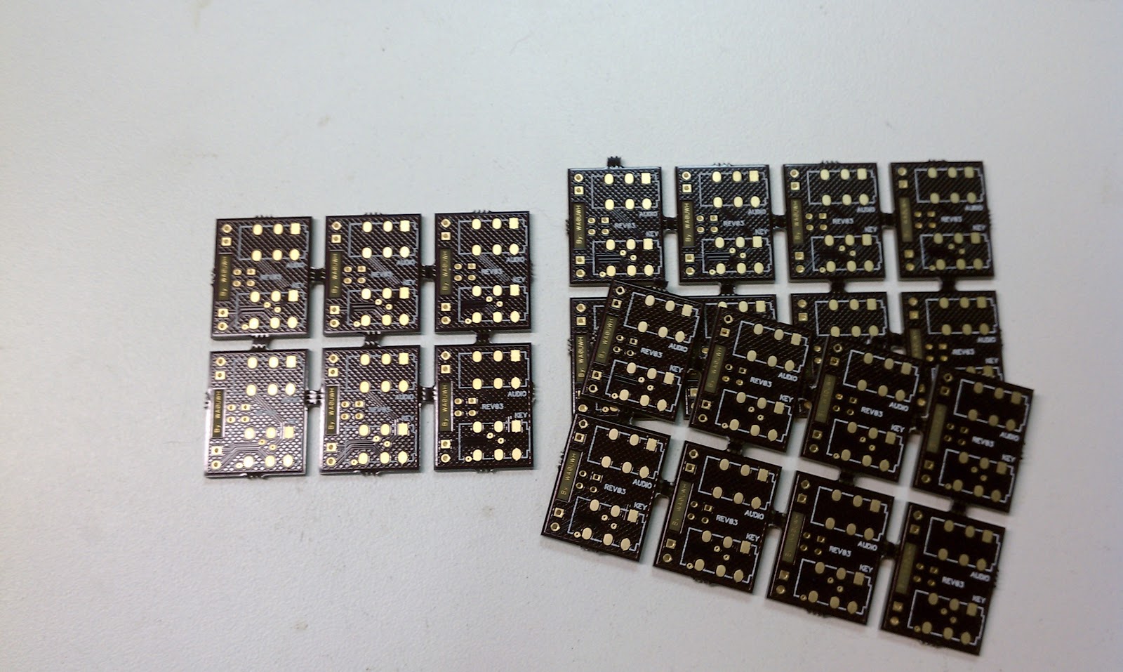
Why So Many Boards,?
Well, . . the PCB Manufactures will not build just one
I have not used the Transceiver in a QSO yet, but the power out measures 0.3 volts p-p at a 50 ohm dummy load (0.3vpp / 2 × .707)^2 / 50 = 225nW, I would have expected more). The tone sounds good on my general coverage receiver, and not too much chirp.

I can hear a received signal, from my MFJ-269, but the receiver sensitivity has not been measured. The receiver does not seem to suffer from hand capacitance normally experienced with Regen Receivers, maybe that is an advantage of; the circuit design, or the small size of the circuit and board.

With 9 volt Battery appropriate bias, more power and sensitivity may be obtained, note the original circuit was designed for 12 volts. In the next few days more performance data collection, experiments and on-air tests are planned. My friend Jeff - KO7M has a spectrum analyzer, so the next time we get together I will have a harmonic content report.

Other implementation of Chirpy can be found via a google search.

Thanks Roger, for this neat "little" Chirpy Circuit Design

And hopefully Roger,  you will forgive me for "expanding" the component count with the on-board Low Pass Filter, Key and Audio Jacks, Antenna and Battery headers, and a battery low side by-pass cap.


UPDATE
I have had several requests for boards or kits, the board would require re-lay-out to correct some spacing issues, proper documents would need to be prepared. I am not sure many people would want to build at this scale. I would like to make a kit available, but price and postage would not support much effort for only a few sales.

--

Sunday, October 25, 2009

A WSPR Transmit Engine

Among my many other projects, I have been thinking about building a WSPR Transmit Engine, a self contained module, that could be paired with a (simple or complex) Oscillator/Transmitter on any band.

I really want to follow G3XBM and G4ILO's leads and get on other interesting bands with a simple configuration.

My initial goals, desires or ideas for this modulator/controller are:
  • Self contained module
  • PIC or other controller
  • Simple rotary Input for CALL, Grid and Power
  • Display for interaction
  • Maybe an output to set Power on Transmitter
  • Provide Audio FSK and/or DC level for direct modulation
  • Transmit Control as necessary
  • Receiver for time tick from (WWV or other) for transmit timing, maybe using the TX antenna?
  • Easy connection to simple Oscillator/Transmitter
  • Simple low Battery power requirements
  • Built with simple and easy to obtain parts
  • Easy to reproduce in Manhattan, Ugly or SMD Style
  • Published Art Work, Source Code and Parts List
Does anyone have any other ideas to consider or as a starting point?


Update1:

Here is what I think I know - more details to be added as they are known - please help if you can.


-

Thursday, October 15, 2009

WSPR Receive on 500kHz

Now that I can run two WSPR stations, one in Tx/Rx and the other in Rx only, I started looking around at other Bands to explore.

I have a few passions; Minimalist Systems, 30 Meters, VLF/LF/MF and K Band.  The 500kHz (600 meters) or the like is something that I have always wanted to explore. G3XBM has rekindled my interest in Med Freq, even though I can only receive. Maybe someone local to the Pacific Northwest has the same interest, I will leave the WSPR receiver on this Band a few days.

Who knows, maybe I will receive WAPR over the pole from Europe.

I will have to look up the Regs for US Ham use of the 600m band, and the lower frequencies in general.

-