Sunday, February 27, 2011

HB Two Sided PCB

Up to this point I have always created single sided PCB using the Toner Transfer Method. I go to a lot of effort to arrange parts to avoid the need for Double Sided Boards. For more complex circuits that is difficult without circuit jumpers.

It is difficult to produce Double Sided PCBs, the lack of the ability to see through the PCB material makes it is difficult to line up the second side art work with precession. Yes, it can be done using pins and holes, but I don't like the idea.

It occurred to me that if the PCB material was exactly the right size, alignment may be possible, but alas, my attempts have failed to provide the precession that I need. I do not like to have to try to cut the PCB material with that high level of precession, and Toner Transfer does not work well near the edge of the PCB material.

Then an Idea!

If common artwork extended beyond the edge of the PCB blank, it could be used for alignment of the second side art, without the need of seeing the pads through the PCB material.

So, now to try it.

I added large makeshift (or crude) Targets around the proposed artwork. As it turns out DipTrace (the PCB software that I use) does not have a Target symbol and all normal "Assembly" art includes component symbol information that over prints onto the PCB circuit layout.

So for my first attempt, I created several large PADs (250 mils) with a large holes (245 mils) and placed them around the PCB, because the pads over print each other the results looks like a clover leaf, shown at each corner of both sides of the layout. Note: this is a small board that is 1 inch wide and 2 inches long. Traces are 8 mils, with 12 mill clearance, the front side ground grid is 8 mils on 24 mil centers.

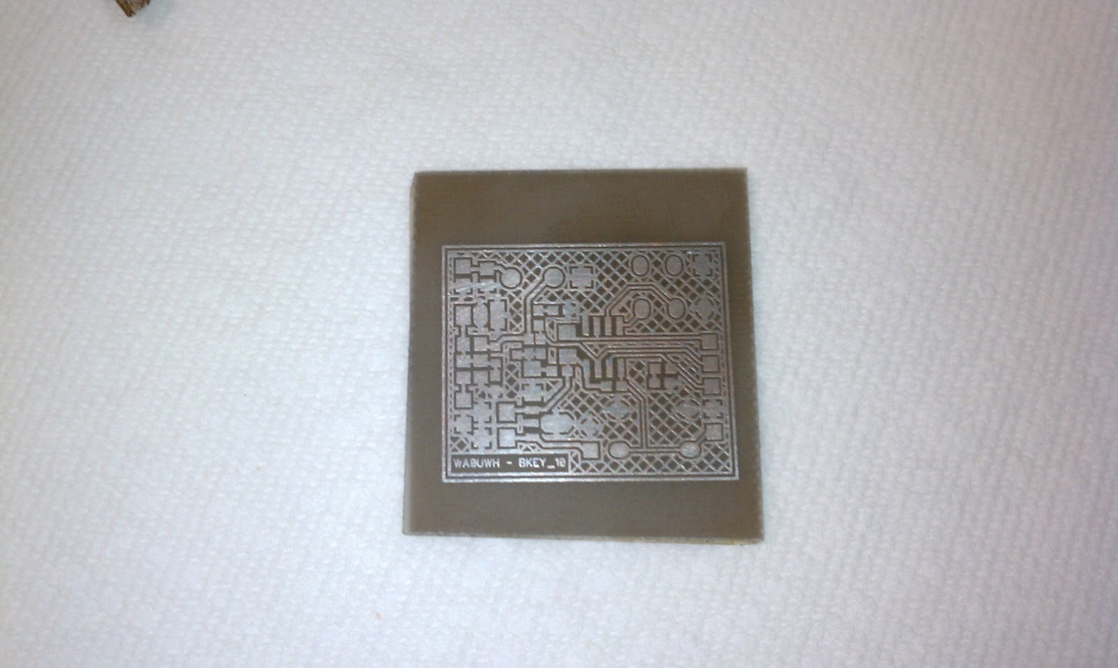
Side One and Side Two Art

Makeshift Targets

The PCB material was cut small enough to not obscure all of the Targets but yet large enough to cover the circuit.

Ready for Lamination

The results are not perfect but usable, the targets did not transfer as well as expected, this is a normal problem near the edge of the PCB material.

The alignment targets are easily usable
for alignment of the second side layout

After the first side has been etched (while the back side was covered with tape), the Targets are used to align the second side art before lamination. If not careful, the lamination process can sometimes slightly shift the art.

Sorry, I did not take photos of the second side alignment process, here are the results after drilling holes while holding a Dremel Tool by hand (I really need to build/buy a hole drilling jig). If you look close (click to zoom in), the errors are my lack of ability to drill accurate holes by hand, and not the art work alignment problem. There a few holes (example, upper center) with good alignment on both sides.

The second side did not print as well as expected, but I am sure that is because I did not wash or clean the second side after removing the tape used as a mask for the first etch.

The smallest of the PCB holes are "via's" which are a 40 mil pad with a 10 mil hole.

After this first experiment, Gerard Yvraut (a fellow DipTrace user) pointed out "Mounting Hole" art prints on all layers as hole art - Just the thing that is needed to make this process easier.

My next attempt will be better.

--

Thursday, February 24, 2011

Another PCB in the Bag

John - KB0ADD, is planning to build an IOIO Antenna and wanted me to build the PCB for the Duplexer. The "KI0AG Micro-Duplexer" design is documented by K0LEE on his web site at: http://k0lee.com/duplexer.htm. John and I chat often about his projects on Google Chat, and on the Sunday Evening EchoLink "QRP" conference call.

It is a cold bright winter day in the Pacific Northwest, just the kind of day for an indoor shop project.

Winter in the Pacific Northwest - Near Seattle
About 30 Deg F

For this project, I used the "Toner Transfer Paper" and GBC Laminator from Pulsar, , and the following "Etch In a Bag" method to produce the PCB, it is fast and easy.

Etch In a Bag

I use a little Ferric Chloride in a Zip Lock Bag, warmed under hot running water - it took about 6 minutes (dependant on the freshness of the etch) for this 1/2 oz copper clad board. Running Hot water over the Bag while etching provides gentle agitation of the etch. A small air pocket within the bag assist in etch movement.

Ready to go to the sink and running hot water
Trouble spots can be helped by rubbing them
through the bag with your fingers
Photo taken at 12:26:49

A Quick Look - Finished and ready for Clean Up
Photo taken at 12:32:21

A Flawless Print/Etch, Ready for Resist Removal
Photo taken after Clean Up and Inspection at 12:39:24

I did not use the suggested "Green Foil" (see Fab-in-A-Box) to cover the Toner, as the laser print was very dark and full, the result was much-much better than I expected.

Clean Up

Normally I store the Bag with Etch within yet another Zip Lock Bag hanging via a clip for later use. Storing the bag vertical prevents the etch from invading the bag zipper.

The Bags that I use are brand name "Ziploc" Heavy Duty Freeze Bags.

I will use Scotch Brite and warm running water to remove the Resist, it is easy and not a chemical mess.

Note: this batch of Ferric Chloride is about spent. The next project will go into a fresh bag and etch.


UPDATE
I did not start with fresh the Etch for the next project (see next post), I was lazy. This old stuff etched a bit slower, but it worked OK with the aid of heat from running hot water over the bag.

--

Tuesday, February 15, 2011

QRSS Beacon

Initial QRSS Project Success

My QRSS Beacon Project is a success (see previous post), it is transmitting FSK on 30m with about 43uW. The onboard K1EL Keyer still needs to be programmed with a Standard Messages, and put into the real Beacon mode - but that will come later. The Keyer works now to send interactive FSK.

QRSS 30m Beacon

The thing that this project adds to my "Family of Marker and Beacons", is message programmability and interactive FSK demo use.

The following capture is from my local QRSS Grabber, the "SEA" message was shorter than my call and was easier to setup for this initial test. SEA is designator for the Seattle Airport. Note: for QRSS each "dit" is sent for 3 seconds - as shown this three letter message is about 50 seconds - but very-very low bandwidth.

The initial Short Term Stability,
and Frequency Shift - Looks Acceptable

The completed demonstration station, with a Key, is as follows. In normal use, the transmitter alone will occupy the inside of a tube, which is used as the center insulator of a 30m Dipole. See the results of my previous experiment.

A 30m FSK Transmitter

The silly (very short) vertical antenna (seen in the close up) provides some coupling and load for demonstrations.

--

More on Fading Labels

Fading Part Bag Labels is a real problem that should NOT exist in this High Tech Information Age, see previous post. Some SMD parts do not have individual nomenclature and are almost worthless when the bag label fades.

I placed an "Open Letter to Mouser" on the Homebrew_PCBs Yahoo Group List, and have received a lot of list user responses. I hated to place the Off Topic letter on the list, but I did not know of another place where so many effected people share.

Maybe, we can get some help with this problem. 

I have updated my previous post with additional information and a few proposed solutions.

--

Monday, February 14, 2011

QRSS Beacon Progress

I have installed the few K1EL Keyer required componenets on the QRSS Beacon Project (see previous post). With so few parts I did not expect any problems, but it is nice to see something working.


That was easy, this is the first video that I have posted via YouTube, it was recorded via my HTC Droid Cell Phone - it was easy enough, maybe more will follow.

--

Mouser Label Fades

I have been buying parts form Mouser for a long time and have a lot of parts, one of the things that I like is the attached label for each bag of components - it is nice neat consistent label, with descriptive, reorder information, and it contains my PO number for that purchase. It is a very nice and useful parts storage and sorting label.

BUT NO!  - one year old Labels are starting to fade - Mouser what is wrong with your bag labels ?????

Most of my SMT parts are less than two years old, some labels are now unreadable. I keep like-parts in plastic tubs, in a heated area of the shop. Light is only provided via over head florescent fixtures and they are only on a few hours a day.

I am not sure what the problem is,
  • Have I caused the problem by my storage method?
  • Is it maybe, plastic out-gas that effect the print?
  • Is the ink supposed to fad away in preparation for land fill?
  • Or, is the paper, or ink just junk? or maybe RoHS?
Soon I will only have hand-written-over labels on my parts - what a BIG PAIN!


Label on the Left is OK
Label on the Right is almost GONE.


Please, Mouser replace your (environment friendly - user unfriendly) label printer, with a more permanent printing solution.

For other Mouser Customers, I suggest you save-your-own-bacon and hand-write on your Mouser Labels until this is understood and maybe fixed.

I DO NOT like having this problem.


UPDATE
I have placed a "Open Letter to Mouser" on the HomeBrew_PCB Yahoo Group List - many list user responses have been received.


UPDATE
When I order parts I always order more than I need, and therefore I always need to store the extras. In the old days, individual parts were easily identifiable with large lettering or color codes. With SMD parts, bag tag labels are very important to help manage and store parts - very small SMD parts without bag tag labels are almost worthless.

I think there are three or four solution to this problem, with my prediction of possible success:
  • 2% - Part vendors will understand the problem and update to better printing equipment.
  • 95% - We users will print on our received labels enough information to get by.
  • 10% - Part vendors will provide Tag Printing option directly from their web site. Mouser has a "Order History" page where an additional printed format could be added to print labels. Two print options already exist.
  • 20% - Someone will produce an App to extract information from an online source to produce labels
  • 40% - The first part vendor that helps solve this problem will see an up shift in market share. 


UPDATE
Here is my on-line Chat with a Mouser Rep (or, maybe a bot?)
Chat InformationPlease wait for a Web Chat Representative to respond.
Chat InformationYou are now chatting with 'Tamara'
Tamara: Good Morning Eldon, how may I assist you?
Eldon Brown: Hello Tamara - I have a problem,
Eldon Brown: After several years of ordering parts from Mouser, and carefully storing my small SMD parts,
Eldon Brown: in containers with the Mouser Shipping tags on each for later referance,
Eldon Brown: I now find that the Tag has Faded and can no longer read it. All other hobby people like,
Eldon Brown: myself have the same problem. 
Eldon Brown: Can Mouser Help - maybe use better ink on part tags? or,
Eldon Brown: maybe provide a Tag printing method from the order history screen, that would print labels on our own printer?
Tamara: I do apologize that you have experienced this, however at this time I am not able to print labels.
Eldon Brown: Are you real, or a bot? I do not need you to print the labels, I am asking if Mouser would concider adding a print function on the Order History Page to print laser Tags on my printer, It would help when I reorder.
Tamara: I can forward your request to my manager to see if we are able to print the labels for you.
Tamara: Can you please provide the part number and invoice number that it was purchased on.
Eldon Brown: This is an example, 12/15/2010-25011794, I would like a print option, so that I can print part labels on my laser printer.
Eldon Brown: I would consider moving to another part vendor, it they provide easy access to part label, I would like Mouser to be first to solve this problem for all user.
Tamara: I have spoke with my manager, this is a request that we will have to forward to our IT department to see if it can happen.
Eldon Brown: Thank you - that would solve a problem for many Mouser Users, See: http://wa0uwh.blogspot.com/2011/02/mouser-label-fades.html
Eldon Brown: Thanks,
Eldon Brown: ELdon
Tamara: You're Welcome
Tamara: Is there anything else I may assist you with?
Eldon Brown: No thanks, I hope to see action soon, Good by.
Tamara: Thank You for chatting with Mouser and have a nice day.
Chat InformationChat session has ended.


UPDATE, GOOD NEWS
Mouser has responded on Aug, 23, 2011, see my post at: http://wa0uwh.blogspot.com/2011/08/mouser-fixed-component-bag-labels.html


--

Sunday, February 13, 2011

Back to Soldering

I have been having fun with the FUNcube (see previous posts) and ignoring my soldering iron lately, to solve that problem I decided to complete the design of my QRSS Beacon. This project has been in the  design stage for sometime, I have been working on; Designing the Circuit, Finding Parts, Creating the Schematic, and PCB layout.

This is will be the first of two Beacons using this design:
  • The first is a prototype or proof of concept
  • The second (if all goes well) will be mounted within an insulator of a dipole, or maybe launched with a balloon.

For this design I am using a K1EL Keyer, which with be programmed with a CW KEY and then put into QRSS Beacon Mode.


As stated before, I enjoy building very small projects:

"As small as I can - to see if I can - as long as I can, . . . see"

I have created similar QRSS Beacons before, this is the first which can be programmed just before use, or used interactive via a CW Key for demonstrations.

This board measure 1.25 by 1.05 inches. The small traces are 8 mils, clearance 12 mils, the text font is 3pt, the ground grid is 8 mils on 36 mil center. I wanted the board to be only 1.0 inch wide, but just could not squeeze the last .05 inches from the width.

So far, as reported here, I have created the board using Toner Transfer, and plated it with solder wipe. Parts with be added for the next blog post.

After Lamination, All Goes Into Warm Soapy Water


Toner Transfer Paper Floats Away

Previously I have normally use a soft spoung brush method of etch, this time I am going to try something new (as seen on the web) - I going to try the "Etch in a Bag" method.

Ready for Etch

Etch in a Zip Lock Bag

With this method, it is easy to watch the progress and mix the solution

I found this method very easy and uses very little etch. I was able to heat the etch while in the bag, by running hot water over it - it etched the board very fast. Also, I noticed that it is best to NOT allow the etch near the zipper - it will creep out while zipping and un-zipping, and will make a mess.

Ready for Resist Removal, I use warm running water and Scotch Bright


Solder Wipe with lots of Rosin

Solder Wipe is done by sliding a short section of Solder Wick over the traces with the tip of the soldering iron. With very little solder on the wick, solder coats the traces, and excess is removed by the same wick in a wiping action. This is best done in the presents of plenty of rosin flux.

After clean up; with Alcohol and more Scotch Bright (to remove solder shine), and a new thin layer of Rosin for protection. If un-removed, the solder shine is very distracting while placing components.

Ready for Trim and Parts

Note: I may have rubbed too aggressively while removing the shine, as the solder wipe is now very thin.

Total time from laser print to finished board:  about 20 minutes.

Note: Unlike all previous posted photos on my blog, for this post I used my HTC Droid Cell Phone Camera. It looks like I could use a Macro Adapter for the phone - I will look into its availability.

--

Saturday, February 5, 2011

FUNcube with HDSDR

As stated in the previous post, I now have the FUNcube working as recommended, with "WRplus" and Firmware 18f.

But, I like the "HDSDR" interface better than that provided by "WRplus". I use "HDSDR" for all other SDR projects and products (i.e, SoftRock).

HDSDR provides multiple VFO's (A and B), up to ten notch filters, and can displayed with other desktop windows.

So, while experimenting with FUNcube, I copied the "WRplus" suggested "ExtIO_FCD_GOMJW.dll" into the "HDSDR" program folder, and started the program.

To my pleasant surprise - it WORKED!

Also,  with more digits, "HDSDR" appears to tune the full range of the FUNcube (64 -1700MHz), above the "WRplus" limit of  999MHz. A signal source and more testing is needed.

Note: "HDSDR" and "WRplus" are both spin-offs or modification of the original "Winrad" program.

Unfortuantly via some of my experiments, I have messed-up (or reset) the I/Q balance parameters, therefore currently the decoding is not working very well - I just need to find more doc's to make the adjustments - more information will be posted here.

I still need to figure out how to calibrate the FUNcube LO - the NOAA Weather Station of 162.55MHz is reported 6kHz off frequency - more things to read and learn.

More experimentation is needed with HDSDR and FUNcube to verify they will really play together.

Currently all of my use of HDSDR and FUNcube is on MS Windows XP, my goal is to have all of this working on Ubuntu 10.10 workstation.


- Follow the FUNcube Label Link below to follow ALL of my FUNcube adventures.


UPDATE:
I understand the WRplus is no longer available for Free, and older copies have now expired and no longer work.


-- Home Page: https://WA0UWH.blogspot.com

Friday, February 4, 2011

FUNcube - Fun

I got my FUNcube working with MS Windows XP using WRplus and Firmware 18f.

Now, changing the received frequency is a simple flick of the mouse wheel, while the cursor hovers over one of the LO frequency digits.

So now - the FUN begins!

The first test was to listen to the local 2m Repeater on 146.82MHz, and then the obligatory 162.55MHz NOAA Weather Station. For each the FUNcube reported the frequency was off by about 6kHz - which suggests that I need to Calibrate the FUNcube LO - just as soon as I figure out how with the new control interface?

I found the following Band Plan Chart useful while using the FUNcube.


With the wide receive frequency range (64 - 1700MHz) of the FUNcube you need a "Program" listing. I plan to collect detailed frequency listing as they are found.


UPDATE
Jeff - KO7M, found this interesting Frequency Reference List for authorities and agencies around the country, it includes the Trunking Frequency Lists. 
http://www.radioreference.com/apps/db/


UPDATE:
I understand the WRplus is no longer available for Free, and older copies have now expired and no longer work.


- Follow the FUNcube Label Link below to follow ALL of my FUNcube adventures.

--