See below
I purchased several Esp8266 Esp-12 modules with Adaptor boards, but found that the Adaptor boards are not very Protoboard friendly, that is, when put on a protoboard there are NOT any open (uncovered) hole locations for Jumper Pins. As shown below.
 |
| Note: All Holes for Jumpers are Covered by the White Board |
This is what I have created for the Esp-12, it has 9 pins with 2mm spacing on one side and 100mils spacing on the other.
I have made this Adaptor Board a Shared Project for your use at OshPark.com, see Link. Let me know if you find it useful.
The Adaptors are very inexpensive, 3 for $1.00, I suggest ordering them in groups of 12 or 24. The larger count makes the postage and PayPal charges more tolerable for OshPark.
Mounting Configurations
The Castellated Edge Connector needs to be cleaned and "de-burred", the manufacturing process leaves fibreglass dust and burs of metal from the inside of the hole that was cut to make the Castellated Edge Connector.
 |
| Clean and Match the Castellated Edge Connector |
 |
| Align and Solder Header Pins |
 |
| All Finished |
 |
| The Flat Wing Configuration |
An Unplanned Back-to-Back Configuration
But, . . . while playing with this Flat-Wing Configuration, I notice that if I reverse the two boards the Esp-12 fits very nicely on top and leaves most of the Protoboard Jumper-pin holes available. I clipped the Header-pins very close (short) with very sharp clippers. And then, just for good measure and avoid shorts, I put tape on the back side of the Esp-12 board.
 |
| Adaptors Back-to-Back |
 |
| Esp-12 Soldered to Back-to-Back Adaptors |
 |
| Esp-12 Read for Use |
 |
| Or, Ready for 8-Pin DIP Socket |
The Family
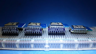
Here is my (new) current family of Esp-12, ready for action.
 |
| The Family |
BTW, I have a Esp-13 Adaptor being manufactured, more on this later.
UPDATE:
I like the Back-to-Back Configuration so well, that I plan to create yet another adaptor, it will be a single board Back-to-Back Adaptor - details to follow.
-- Home Page: https://WA0UWH.blogspot.com


You my friend are the crazy-cat-guy of ESP addicts... :)
ReplyDeleteGreat little project! I was going to order the adapters, but if you plan on having the sing board adapters shortly, maybe I'll hold off. Have an ETA?
ReplyDeleteI have now shared The Single Board Esp12 and Esp13 Adapters on OshPark.
Delete