Thursday, January 31, 2013

PA47 Now Ready for On The Air Tests

Thus far I have NOT connected my PA47 Amplifier to an antenna, because I was not sure of it output harmonic content (see previous posts).

Last night at our monthly P&C group meeting, Wayne - NB6M presented a demonstration of his new DSA815 Rigol Spectrum Analyzer with one of his oscillators and the effects of a output filter devices. His filter completely eliminated (down into the noise floor) any harmonic content.

As a second example and demonstration, I provided the PA47 Amplifier and a LowPass filter. A 50 Ohm load and 40db tap was used to reduce the input to the Analyzer. Actually, both the 1 Watt and the 15 Watt versions of the PA47 were checked, the results were about the same.
The 1 Watt and 15 Watt Version of PA47
The output filter that I used, is a simple Chebyshev 5 Pole Filter (as previously posted).

30m LowPass Filter as Designed with LtSpice
The filter was originally designed via an Online Filter Design program, and then available multiple 330pF 1206 SMD caps were used to obtain the nearest values, 3 caps for each end, and 4 for the center. The cores were wound as necessary by measuring the results on an AADE LC meter.

30m LowPass Filter as Implemented
The Results

Wayne declared the PA47 fit for Amateur Radio Service. The second harmonic was down 51db and the third was down 67db from the fundamental.
PA47 Connected to
DSA815 Rigol Spectrum Analyzer
I will soon connect the 1 Watt version of the PA47 to an Antenna, and use if for QRSS Beacon Service on 10.140050MHz (+-50).

--

Monday, January 28, 2013

More 0402 Thermistors

In preparation of loading and testing the next revision of my PA47 Amp, I have started the process of joining FET and Thermistors, by mixing the glue - JB-Weld epoxy (see: previous posts).

For this build, I am using only JB-Weld, for the initial tack and then for the final cover. The JB-Weld web site provided some interesting data regarding strength and temperature resistant abilities. It suggests that JB-Weld is the right "glue" for this Thermistor attachment process.

It appears that a little too much of JB-Weld was mixed, but is actually is just a small drop, most of it will not be used.
Microscope at 7X

Here are some FETs with Thermistors attached with small mounts of JB-Weld. Soldered wires will be added after the epoxy has set.

2N7000 with Thermistors Attached

While under the Microscope I noticed that JB-Weld is not what it appear to the un-aided eye, it is actually gray with black flecks.
This the same as the First Image, only the
Microscope Set at 15X
After curing, this glob of epoxy was subjected to a test with a hot soldering tip, confirmed that JB-Weld is much more heat tolerant than Hobby Fast Cure Epoxy.

--

Thursday, January 24, 2013

Use of a 0402 Size Thermistor

This post and project is keeping with my On-Going Goal of working on very small projects as long as my eyes and steady hands allow.

The Thermistor Fan Control Circuit is working very well for my PA47 RF Power Amplifier (see selected links to previous posts). The PCB was re-laid out to include the circuit. Initially for testing, I just used an available 10K NTC Thermistor super-glued to the heatsink on a 1 Watt PA47 configuration.

For this project, my plan is to attach a small 10K NTC 0402 size thermistor directly to the 2N7000 for best FAN Control and cooling of the FET.

Here are some Microscope photos of the attachment process.

Shown is the 0402 Thermistor super-glued to the back of the TO-92 2N7000, along with the tip of a standard X-Acto Blade (for additional size reference).
Attached 0402 Thermistor on a TO-92 2N7000
Wire Wrap Wire (30 AWG) was then soldered on each end of the Thermistor.
Thermistor with Wires Attached
A small drop of Epoxy was added to cover the connections and support the attached wires. Epoxy does not stick to the Kynar (wire insulation) very well (if at all). The wire connections may need better/more support.
Waiting for the Epoxy to Cure
I used Fast Cure Hobby Epoxy, but it will take over night to harden completely, in circuit testing maybe started tomorrow.

I am not sure of the thermal conductivity of Hobby Epoxy, perhaps something else would be better? Maybe another harder Epoxy such as JB-Weld?

This is ALL probably not necessary, but I wanted to see if I could do it. For future projects and use of Thermistors will probably be a larger size, and maybe not attached directly to the FET.

--

Wednesday, January 16, 2013

Part Quest

I am always looking for Small Parts for my projects.

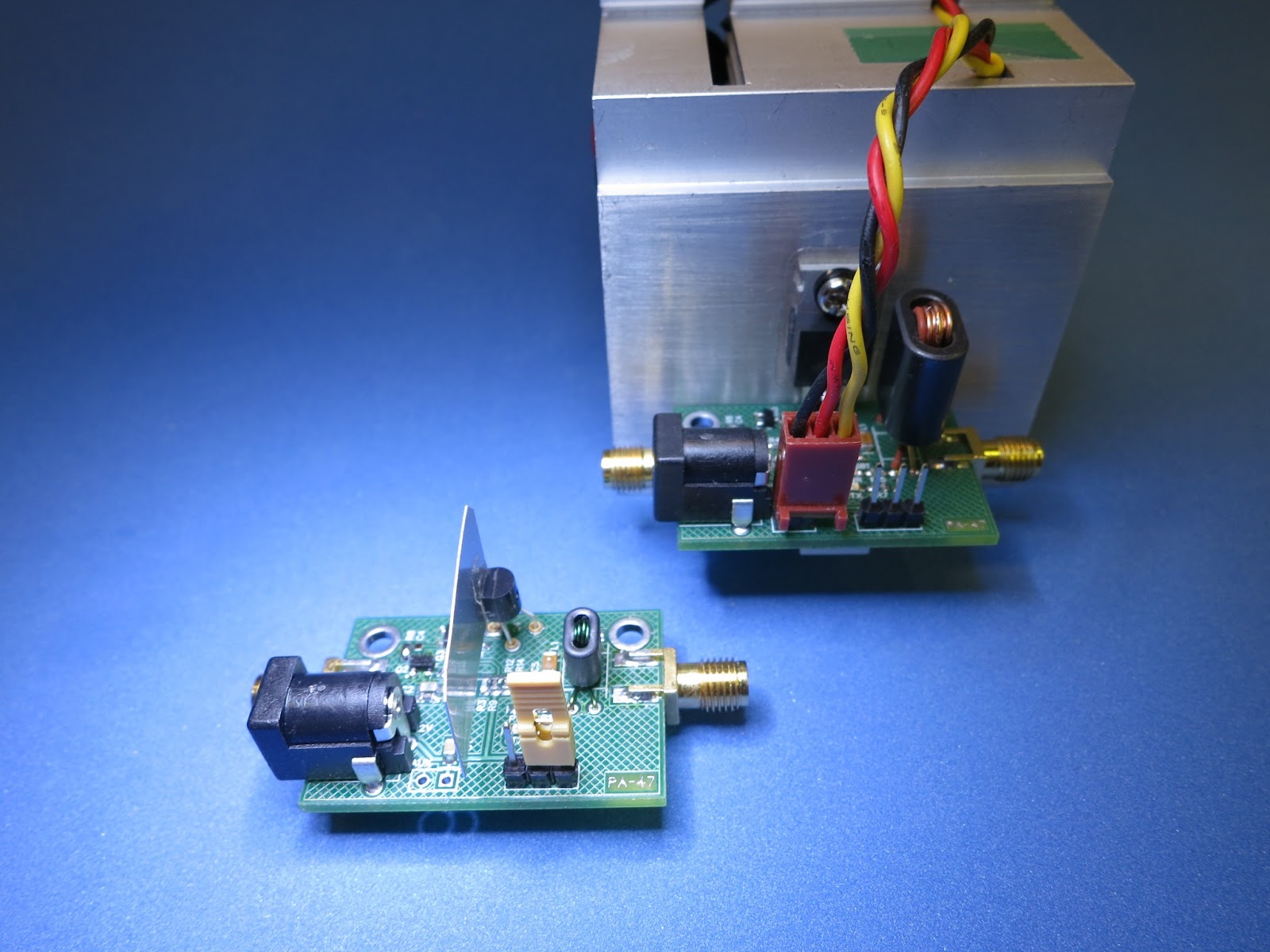
For most of my projects I have standardized on a simple Battery connector, it is the same style that is used in many of the Propeller and Arduino Products. The connector is shown here attached to my PA-47, which is a Homebrew 15 Watt HF PA.
The Battery Connector on 
My PA-47 Project

The actual connector that I have been using is a little different than those that are readily available. This connector has smaller tabs that are used to solder it to the PCB. Because the tabs are smaller, this same connector can be use with proto-breadboards (with only a little difficulty) . The tabs are not exactly the size the breadboard would like. but it works. Also, because the pins are little smaller they fit into round drilled holes in the PCB. Note: Most of my PCB suppliers do not allow plated slots as necessary for many other battery connectors.
My Favorite DC Connector
for  Projects
(unknown to me at the time,
this is a PJ-102A)

My stash of these connectors is almost depleted. Somewhere along the way, I got the (wrong) idea that these connectors were called "PJ-007".


A quick (causal) search via FindChips found the PJ-007 was only available from Digi-Key, I had several other parts that I had planned to order from Digi-key, so I ordered 20 each PJ-007's, for about $12.00


 The True PJ-007


Received, BUT NOT!  what I wanted !

I received the PJ-007's, they are a similar style of connector, but they are about 1/2 the size that I was expecting. My quick and "Causal" search was too quick - now I have a bunch of very small connectors that I will probable never use.

I would have to look to my other suppliers and/or try to remember where I had previously purchased the desired connectors.

After several days of searching and trying to remember, I eventually found my source at Adafruit. But, the search of the Adafruit site was not exactly easy, as this part did not match any key words that I tried. I finally gave up and looked at the complete list of available parts, but still no joy.
https://www.adafruit.com/products/80

I eventually found the connector on the Adafruit site as a "suggested part", while viewing the available 9 Volt Battery Clips (which is a nice clip with wires and a end connector).

But Adafruit description of the "suggested part" did not include a manufactures part number, there was just an order ID number - 373. I plan to add a few to my next Adafruit order.


But then:

While attempting to re-layout my PA-47 Board to correct and add some new features, I did a quick check of ALL of the parts and patterns before ordering a new set of boards. While looking at the Library part for the Battery Connector, I noticed that it included a spec sheet and URL for the connector. With a little research of the manufacture I found the desired part is a PJ-102A. A quick check of FindChips.com suggested the part is available from several suppliers.

Several PJ-102A are now on order.

Until next time, my small Parts Quest, . . .  goes on.

--

Sunday, January 6, 2013

My Online Password Management Solution

In the past

Managing my Online Account Passwords has been a time consuming tedious task. For the last few years I have tried many methods, and recently used a simple spread sheet, which was only available on one of my shop computes.

Because of fear of loss, exposure and/or theft, I have always typed my passwords into the spread sheet in simple (and crude) obscure format, that only I could mentally decipher (maybe).

Yet, I have always been concerned and nervous about password theft.

But Now

I have recently found "aWallet.org" which is an APP for my Android Cell Phone. it provides true AES/CBC "high level security" for my online Account Passwords. And, an emergency encrypted backup file can be created. For safe keeping, I copy the encrypted backup file to DropBox (a free cloud service). Because the backup is encrypted with a 256 bit encryption key, the data is safe on an un-encrypted online storage service, they claim it would take millions of years to crack the file.  For additional security, I use several files that are known as a HoneyPots.

With the DropBox phone APP, I can copy to the cloud the encrypted backup (of the password data) with a simple push of a few buttons. The backup file is then available on all of my connected DropBox computers. DropBox also has an Archiving Function that allows you to reclaim; deleted, lost, or previous versions of the files (within 30 days).

This is completely SAFE, I trust it even for my Banking passwords. If I lose my phone, the data can not be viewed without a "master pass code" (which is stored internally with the same encryption level). If you are still really concerned, you can elect to NOT make copies and/or optionally set up the aWallet pass code to "auto destruct" the Encrypted Password files if too may unlock attempts are tried.

If I buy a new phone, the DropBox copy of the encrypted file can be downloaded to the new phone and therefore used the same as before.

Note: as with any encrypted storage it is only as good as the secrecy of the "master pass code", make it unique from ALL other passwords, and ONLY known to you!

BTW: if you do not use DropBox - you SHOULD!

Dropbox is useful for many things, more than I can relate here (I use Dropbox for all of my projects reported on this blog). When you join, you get 2GB of VERY easy to use Cloud Storage space for FREE. Ask me for a DropBox Invitation, we each will get an additional free 500MB of DropBox storage space. If you install from the web without a friendly invitation, you will NOT get the additional free space. Send your request to my e-mail address as shown on my www.QRZ.com page. with subject: "DropBox Invitation". Encourage your friends to join DropBox and you and they will each receive additional 500MB of free space.

Besides, where else would you store all of your Ham Radio Online Passwords, for; QRZ, ARRL, qsl.net, etc, etc!


I am now a, very calm, Online Password - Happy Camper !


UPDATE

The new version of aWallet is available, aWallet-Cloud automatically does an encrypted backup to your Cloud server.


--

Saturday, January 5, 2013

An Open Post to DipTrace for Menu Enhancement

As I have stated before, I use DipTrace for most (if not all) of my PCB projects posts on this blog. The major reasons that I use DipTrace are:
  • I have a very small investment in Licenses.
  • DipTrace runs well on my Linux workstations via WINE  (I do not have access to MS system).
  • DipTrace provides one of the best High Resolution Copper Pours that I have found.
  • DipTrace's recent Updated Software has solved many of my previous grips, see my DipTrace Survival Guide post.
  • DipTrace is easy to learn and easy to promote to new users.
  • Managing your own Library of parts is easy, once you learn all of the tricks.
With the latest DipTrace Software Update, and with the press of a single button, High Quality PCB's can be ordered (it is almost too easy, especially if you order before your are actually ready?). The included BayArea Circuits PCB Manufacturing Service is not the cheapest, but they are one of the fastest available in the USA,  they claim the default is 5 days plus post delivery time (and faster if you want to pay more).

The following is my recent Enhancement Request as posted on the Yahoo Group DipTrace Forum.


Default Menu Enhancement Request

One of the most accessible menus available with DipTrace PCB Layout is the "Right Mouse Click". The Default Menu is available when nothing is selected and available virtually at any place on the entire Display screen.

But, this severely under utilized Default Menu has only has two menu items available for selection; "Paste" and "Empty Clipboard", both of which I have never used.

I would like to see the following items added to this Default Menu:

0) ESC
1) Update ALL Copper Pours
2) Edit Traces
3) Route Manual(~)
4) Auto "ReRoute" Trace
5) Mirror while Bottom selected (very useful for backside edit and viewing)
6) F10

I know some of these are available at the Keyboard, or at the top menu, but productive is LOST with each long mouse excursion or attention diversion to the keyboard.

Currently, to use DipTrace, my left hand hovers over the ESC and 1,2,3,4 keys as these key functions are almost always needed to do anything. But other keyboard activity requires diversion of attention and could be best handled via menus.

NOTE: The above menu items are only a few that I would put into a "User Defined Menu" if the function was available.

There may be other menu items that other uses would suggest for this Default Menu.

Regards,
Eldon Brown


I am hopeful that we will see more Productivity, User Menus, and Library Access enhancements in the near future releases.

--

Friday, January 4, 2013

More Destructive Testing

But, . . . hopefully NOT.

With the breadboard FAN Control Circuit designed and working, I decided to do some more Destructive Testing of the PA-47 (see previous post).

The two tests that I had in mind were to; subject the PA to High VSWR, by; first, opening the end of the 18 inch coax, then second, putting a "short" on the end. These are the two extremes.

Initial Test - Normal Operation
  • The PA and exciter were configured for normal operation of 12.6VDC.
  • The Exciter provided 12 mWatts of drive at 10.140MHz to the PA input connector.
  • The PA with Low Pass Filter were connected to a proper 50 Ohm Dummy Load via a 18 inch coax cable.
  • DC input was 12.6 VDC at 2.54 Amps, or  32.1 Watts.
  • Voltage measurements are taken at the output of the Low Pass Filter.
  • The typical Low Pass output voltage is 75 Volts PP, or 14.1 RF Watts output.
  • The FAN Control Circuit turns the FAN slowly.
  • All is normal.

The Open End Coax Test
  • DC input was 12.6 VDC at 1.34 Amps, or  16.8 Watts.
  • The measured Low Pass Filter output voltage was 160 Volts PP.
  • The danger here is the reflected voltage will exceed the voltage rating of the RF Power FET.
  • Results: No apparent harm was done.

The Shorted End Coax Test
  • DC input was 12.6 VDC at 3.11 Amps, or  38.2 Watts.
  • The FET was getting HOT!
  • Immediately the FAN Control Circuit put the FAN into Full High Speed mode.
  • The measured Low Pass Filter output was 35 Volts PP (note: this is about 18 inches from the short).
  • After about 10 seconds, the FET went into a kind of internal thermal shutdown on its own (I did not expect it to do its own shutdown).
  • DC input was now 12.6 VDC at 3.54 Amps, or  43.6 Watts.
  • Measure RF output went down to about 10 Volts PP.
  • The PA was left to cook for about 30 seconds. I am not sure how long this could continue without permanent damage.
  • Results: FAN at High Speed, FET was in Internal Thermal Shutdown, everything was getting HOT!

Conclusion

The FAN Control Circuit saved the day, no Blue Smoke was emitted. I think the FAN Control Circuit is a very good addition to the PA-47 !

After Cool Down, the 50 Load was reconnected and normal operation was resumed.

Although, .  . . the idle current is now 80 mAmps, where as before the tests, idle current was typically only 20 mAmps. Maybe the quality of the FET has diminished?


--

Thursday, January 3, 2013

PA-47 with Fan Control

Today I breadboarded a FAN Control circuit for my PA-47 RF Power Amp (see previous post). I used a simple NTC Thermistor for the sensor, which will be attached to the FET on the Heatsink. The FAN Control circuit also supports a slight temperature bias when the TR Relay is activated.
The Thermistor can be seen attached to the FET

The breadboard FAN circuit has be running for several hour - working as expected, it cycles the FAN ON and OFF (with speed control) as the Beacon Exciter transmits on its six minute schedule. The RF output is connected to a dummy load, as I have not looked at the PA signal on a Spectrum Analyzer yet.
The Chaos of the Bench
Testing in Progress

My goal was to build the new PA with the additional FAN Control circuit small enough that it would fit the same 1 x 1.5 inch layout of the current PA-47. I had to rearrange a few parts to make it all fit.

While doing some experiments with a new layout with DipTrace, I tried laying it out as a four layer board. Four layers makes the circuit layout much easier. but it would be a lot more expensive ( about 3 to 4X ).

New two layer PA-47 boards with Fan Control are now on order.

--