Showing posts with label Prop. Show all posts

Sunday, April 20, 2014

Minima - CPU Module Mods

While building my Minima CPU module, and thinking about the circuit's programming interface components. I started wondering if there was an Off-the-Shelf USB product that could replace and simplify the circuit.

After a little research, I found three likely candidates, all available from Parallax.com;


Each have slightly different header pin-outs for connection to a project. Each uses the same FT232RQ USB-to-Serial chip.

For DYI, the FT232RQ chip is a simple "state machine", which does all of the hard work of USB-to-Serial protocol and signal-level translation. It is simple enough that it could be included directly into a project, all that is necessary is; the FT232RQ, a USB connector, and a few resistors (see the Prop-Plug datasheet with schematic). Note: Parallax encourages use of their schematic for DYI implementation, they will be happy to supply the parts, or as available elsewhere.

If the FT232RQ is included directly in a project, the +5V from the USB connector could also be used by the project, only the off-the-shelf 4D Systems USB Programmer (listed above) provides a fifth pin for a power connection.

The FT232RQ is available in the 28-LD-SSOP and the QFN-32 package. I will use the QFN-32, because I like smaller components. The price of the FT232RQ is about $5.00, but that is cheap for what it does and the components that it replaces.

Also, if the FT232RQ is included directly as part of a project, it is available for generic ASCII I/O for control or output via a standard USB connection.

Because I already have a Prop-Plug, I think I will simplify and re-layout the next Revision of my Minima CPU module with a simple Prop-Plug header. I hope this will work as a generic dumb download interface with the Arduino Interactive Development Environmnet (IDE), but this remain to be tested. Does anyone know?


UPDATE: Apr 21, 2014 14:11
As per the comments, Larry has suggested the "FTDI Friend" - $15 from Adafruit.com

--

Thursday, January 31, 2013

PA47 Now Ready for On The Air Tests

Thus far I have NOT connected my PA47 Amplifier to an antenna, because I was not sure of it output harmonic content (see previous posts).

Last night at our monthly P&C group meeting, Wayne - NB6M presented a demonstration of his new DSA815 Rigol Spectrum Analyzer with one of his oscillators and the effects of a output filter devices. His filter completely eliminated (down into the noise floor) any harmonic content.

As a second example and demonstration, I provided the PA47 Amplifier and a LowPass filter. A 50 Ohm load and 40db tap was used to reduce the input to the Analyzer. Actually, both the 1 Watt and the 15 Watt versions of the PA47 were checked, the results were about the same.
The 1 Watt and 15 Watt Version of PA47
The output filter that I used, is a simple Chebyshev 5 Pole Filter (as previously posted).

30m LowPass Filter as Designed with LtSpice
The filter was originally designed via an Online Filter Design program, and then available multiple 330pF 1206 SMD caps were used to obtain the nearest values, 3 caps for each end, and 4 for the center. The cores were wound as necessary by measuring the results on an AADE LC meter.

30m LowPass Filter as Implemented
The Results

Wayne declared the PA47 fit for Amateur Radio Service. The second harmonic was down 51db and the third was down 67db from the fundamental.
PA47 Connected to
DSA815 Rigol Spectrum Analyzer
I will soon connect the 1 Watt version of the PA47 to an Antenna, and use if for QRSS Beacon Service on 10.140050MHz (+-50).

--

Sunday, December 23, 2012

PA-47 At Only 1 Watt

Original PA-47
with Large Heat Sink, 
Matching Transformer
and FET IRF510
In keeping with my goal of making my Homebrew projects as small as my abilities allow and using the same previously created PCB board (see previous post on my PA-47 Power Amplifier)

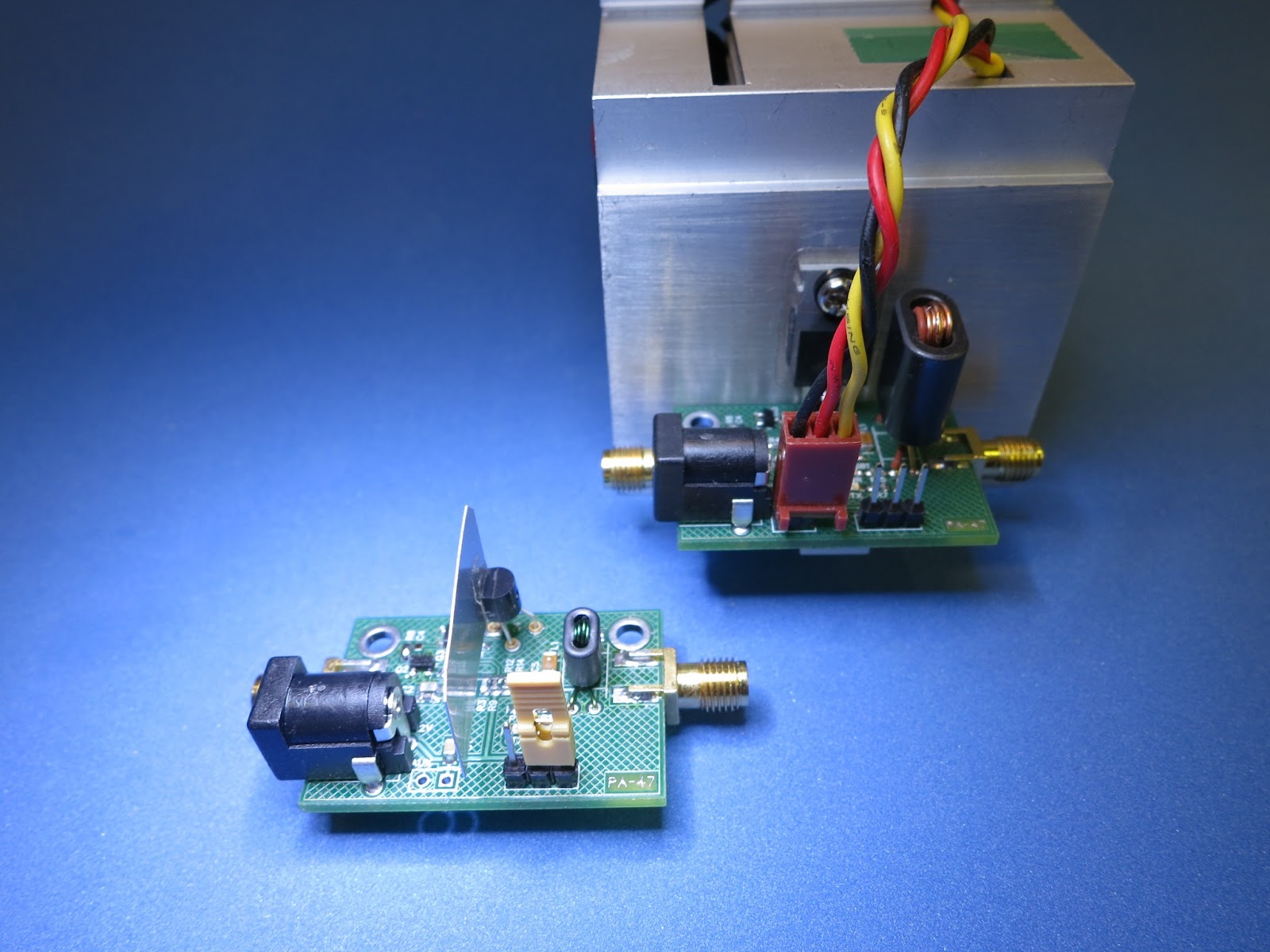
I have reduced the size of the output matching transformer and changed the output FET from a IRF510 (TO-220) to a 2N7000 (TO-92).

New PA-47  Running at
1 Watt Output

Knowing that the 2N7000 would not produce the same 4.7 Watts of the replaced IRF510 with its large heat sink, I planned to reduce the supply voltage; from 12.6 Volt down to 9 Volts, and reduce the size and turns ratio of the matching transformer form 1:3 to 1:2.


New Replacement Parts
of the Original PA-47
are the 2N7000 and 

Smaller Matching Transformer

Initial test produced 1 Watt RF output, and a Very Hot 2N7000 FET. A small 3/4 inch sq piece of aluminum flashing was super-glued to the FET which solved the heat build-up problem. Just in case, I also installed a pin socket for each leg of the FET (which means I can easily replace the FET, if I inadvertently cause it to release its Magic Blue Smoke :-).

For this first test, the DC input was 8.5 Volts (not a very fresh battery set) at 360 mAmps: or 3.06 Watts DC Input, which suggests the PA at only about 32% efficient (more work is maybe needed to increase this). The standby current (no RF input) is about 13 mAmps, and most of that is used to drive the green Power-On LED.

30 Meter Low Pass Filter

Without the FAN and Large Heatsink that was used in the initial PA-47, this PA is silent.

Like the original PA-47 an outboard Low Pass Filter is necessary and was used for this experiment.


TR Relay Mounted Under the PCB

The yellow-tag jumper on the header turns on the TR Relay, which is mounted on the under side of the PCB. Normally transmitter control from the exciter would be connected to this header.

The RF voltage measured at the 50 Ohm Load via the scope: 20 Volts PP, (20/2*.707)^2/50 => 1 Watt, or as per the web  RF calculator.

This smaller and lower power PA will be perfect for my ongoing Propeller 30 Meter Beacon efforts.

After I correct the PCB layout (see previous discovered errors),  and if there is interest, I may make the PA-47  board available, or as a complete Kit (but, as a board or kit, this would not be suited for first time builders, nor a builder without a Microscope).

The Exciter (Driver)
The Exciter
Outputs 12 mWatts

For this experiments and as explained previously, I used my Propeller Transmitter as the exciter which provides 12 mWatts of drive. The Propeller is the second board in the stack.

--

Monday, July 23, 2012

A Friends Voice From the Past

A voice heard from 45 years ago.

Saturday I was reprogramming my Prop Receiver with new User Interface (UI) Code. The previous UI code did not provide an intuitive controls for the BFO and VFO Frequencies with the two knobs that are available. It had previously been a rush-job, just to have something to demonstrate as a working receiver at Salmoncon (which was the previous weekend).

Prop Receiver on the Left

Now, to test and try the new UI code, I connected the Prop Receiver to an Antenna, a 250 foot long wire that I previously posted a blog. For the test I programmed the default Frequency to 20 meters. With a little twisting of knobs I found the sweet spot for the BFO and was tuning across the band. I heard several stations on CW, and then higher up the band on SSB. I tuned across a signal and recognized a very distinctive friends voice from my past, of 45 years ago, Randy - KH6IB.

I switch the antenna over to my IC-730 and tuned up on near the Frequency that I thought was where I heard Randy on the Prop Receiver. My Prop Receiver Frequency was un-calibrated and therefore I had to do a little searching on the IC-730.  But on 14.227MHz his distinctive voice was heard again. I sent BREAK and waited for his QSO to end. Randy asked for the Breakers, I jumped in with my call - "Whiskey Alpha Zero Uniform Whiskey Hotel". Randy came back with, "the Whiskey station please try again". We made contact, and had a short reminiscing QSO before the band went south. This was my first real on-the-air QSO with Randy.

Actually, Several years ago, Randy and I chatted on EchoLink.

In 1967, while in the Navy, Randy and I were attending the Precision Measurement Equipment Laboratory (PMEL) school at Lowry Air Force Base near Denver CO. I think Randy was a little ahead of me in the six month training schedule, but we meet because of his Ham Radio. A few weeks earlier his Mother had sent him his SB-101 transceiver to use in his barracks. Being a previous Novice, I gravitated to the sound of CW and SSB coming from his room. We spent the rest of our tour/training time at Lowery; walking to-and-from the chow hall and class, chatting about Ham Radio, and his race cars. After graduation and leaving Lowry, I was sent to the East Coast to a Submarine Tender and I think Randy was sent to the West Coast and Vet Nam - I never saw Randy again.

Here I am Aboard The Submarine Tender
 H. W. Gilmore AS-16
1968
So for me, Ham Radio has again brought a voice and a friend from the past.

Oh, The Prop Receiver seems to work well, even though I have not checked the receiver sensitivity yet. And, I have not tried to energize the Band Switch Relay and then try the low bands and lower sideband (below the 11MHz IF).

--

Tuesday, July 10, 2012

Prop Controlled Receiver - Success

In the past I have blogged about the QRSS, WSPR, and OPERA Beacons that I have created with the Propeller Microprocessor (Prop). The Processor generates the RF signal that is passed through a LowPass Filter to remove Harmonic, and then connected to an Antenna. For some experiments a Homebrew Power amplifier was used to increase the processor generated RF signal from 7 milliwatts to 150 milliwatts. I have received many reports (or Spots) from many stations around the world. I think the farthest was from Australia at about 12,000 miles. I consider my Propeller Beacon a fun and very successful project.

And Now,  . . .

I have been playing with the idea and trying to receive signals with the Propeller. A simple direct conversion receiver using a SA612 mixer would require a Local Oscillator at the received frequency. The Propeller can generate RF frequencies from; 0 to 128MHz, with an amplitude of about 3Volts Peak-to-Peak. Which is a little more than needed by the SA612, but it can be attenuated with simple resisters if needed.

My original plan was to construct a simple direct conversion receiver daughter board for the Prop. But, Jeff - KO7M pointed out that the N3ZI Double Conversion Receiver using two of the same SA612 chips, was available as a kit (this was actually several months ago). I put the kit on order, and it has been setting around waiting for my User Interface (UI) project to be completed (or at least working). The receiver kit needs two RF signals, one for the VFO and one for the BFO (about 11.055MHz). The BFO is normally supplied by a Crystal. I plan to replace the BFO Crystal with another RF signal from the Prop.

For the High Band (above IF) and Upper Side Band, the injected frequency is the BFO frequency (IF) plus the intended (displayed) receive frequency. For example, for USB: the VFO = BFO + Received Freq, for LSB: VFO = BFO - Received Freq.

For the Low Band (below IF) and Lower Side Band, the injected frequency is the BFO frequency (IF) minus the intended (displayed) receive frequency. For example, for USB: VFO = BFO - Received Freq, for LSB: the VFO = BFO + Received Freq. (I think that is correct?)

Obvious the VFO should be adjustable so the receiver can be tuned to the desired received frequency. But, maybe not obvious, is that small adjustment of the BFO can be used to adjust the band width of the received signal. In both cases a handy way of adjusting either or both frequencies is necessary. And that is where my UI comes in, it has knobs and buttons that can be programmed to control two Prop RF signals which will be supplied to the receiver.

Note: Sadly, I think the N3ZI Receiver Kit is no longer available.

Prop Controlled Receiver - Left
Prop Transmitter - Right
Today's Success !!

I have one Prop running ko7m's Keyer Program and another controlling the double conversion receiver. The test distant between the transmitter and receiver was only about 12 feet, but it works !

With the receiver connected to an antenna, I have received other signals with this set up; WWV and other Amateur stations.

The Receiver is mounted under the Prop on the left, the two SMA coax cables connect the VFO and BFO. Two of the corner holes of the receiver match the hole pattern of the Prop board (nice). The Keyer Transmitter is on the Right.

This weekend at Salmoncon, Jeff and I will demonstrate some of our Prop projects. Maybe, we will have time attempt to do real QRP DX'ing with our Props.

Many more experiments and improvements are planned.

For now, . . . it all just, fun and games, with the Prop !!

--