Friday, July 24, 2015

Esp8266-Esp12 Adaptors

UPDATE:
See below

I purchased several Esp8266 Esp-12 modules with Adaptor boards, but found that the Adaptor boards are not very Protoboard friendly, that is, when put on a protoboard there are NOT any open (uncovered) hole locations for Jumper Pins. As shown below.

Note: All Holes for Jumpers are Covered by the White Board
And besides, I wanted to create my own adaptor, similar to the Esp-11 Adaptor created earlier (see previous post).

This is what I have created for the Esp-12, it has 9 pins with 2mm spacing on one side and 100mils spacing on the other.

I have made this Adaptor Board a Shared Project for your use at OshPark.com, see Link. Let me know if you find it useful.


The Adaptors are very inexpensive, 3 for $1.00, I suggest ordering them in groups of 12 or 24. The larger count makes the postage and PayPal charges more tolerable for OshPark.

Mounting Configurations

One board is used for each side of the Esp-12. They can be used in several configuration (including one that I had not previously thought of, when creating it, more on that later).

The Castellated Edge Connector needs to be cleaned and "de-burred", the manufacturing process leaves fibreglass dust and burs of metal from the inside of the hole that was cut to make the Castellated Edge Connector.

Clean and Match the Castellated Edge Connector
Align and Solder Header Pins
First, Header Pins were Aligned and Solder , they were later pushed into a Protoboard to help align the Esp-12 on top. Note: the Header is NOT soldered through the holes in this configuration.

All Finished

Another configuration uses the Adaptor parallel with the Esp-12 and with the Header soldered in the holes as normal.

The Flat Wing Configuration
I do not care for this parallel Flat-Wing Configuration, for the same reason that I do not like the original purchased adaptor, it covers all of the Protoboard Jumper-pin Holes (not protoboard friendly).

An Unplanned Back-to-Back Configuration

But, . . . while playing with this Flat-Wing Configuration, I notice that if I reverse the two boards the Esp-12 fits very nicely on top and leaves most of the Protoboard Jumper-pin holes available. I clipped the Header-pins very close (short) with very sharp clippers. And then, just for good measure and avoid shorts, I put tape on the back side of the Esp-12 board.

Adaptors Back-to-Back
The Esp-12 is aligned and then soldered on top.

Esp-12 Soldered to Back-to-Back Adaptors
Esp-12 Read for Use
Or, Ready for 8-Pin DIP Socket
Note, with this Header-pin spacing, this would fit into a normal 8-pin DIP socket !

The Family

Here is my (new) current family of Esp-12, ready for action.
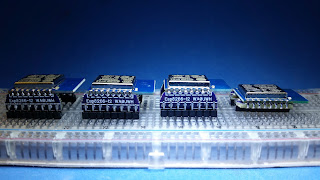
The Family
Let the Esp Programming Fun Begin, . . . Again !! :-)


BTW, I have a Esp-13 Adaptor being manufactured, more on this later.


UPDATE:
I like the Back-to-Back Configuration so well, that I plan to create yet another adaptor, it will be a single board Back-to-Back Adaptor - details to follow.


-- Home Page: https://WA0UWH.blogspot.com

Sunday, July 12, 2015

Esp8266-Esp11 Adaptors

UPDATE:
See below

I prefer the Esp8266; Esp11's and Esp12's for my projects, but interfacing to tightly spaced pins can be challenging. In past (see previous blogs) I have used several methods to make the connection to the edge "Castellated" pin-outs.

What is needed is an adaptor for the Esp11's 1.27mm (50mil) pin spacing and the standard 100mil protoboard spacing.

The following is my solution for the Esp11, a small board produced by OSHPark.com. I have made this board available for your use via a shared project, at:


Let me know if you find these useful, Thanks.

The Adaptors are so inexpensive, 3 for $1.00, that I suggest ordering them in groups of 12 or 24, the larger count makes the postage and PayPal charges more tolerable for OshPark.

A group of Adaptors
Ready for Solder
Castellated Connector
The Castellated Connector is created by the manufacture by routing (cutting) though the centre of a plated hole.

Note: the hole conductor is slightly "curled" (distorted) by the cutting process, but that is not a problem as the curl will be encased in solder when used.

Pin Alignment with Esp8266-Esp11
The Pin Pitch is 1.27mm (50mils)
Solder Is Used as Jumpers
The Solder Jumpers are very strong and durable, and perhaps making the joint stronger than the fiberglass PCB itself.

Solder Jumpers were Installed in Groups
Pin Headers (100mil) are Added
Ready for Use
These four Esp's are now ready to be used on my protoboard.

Some of my Esp projects are available online, see previous posts.


-- Home Page: https://WA0UWH.blogspot.com


Wednesday, July 1, 2015

Esp8266 - My Experimental WebServer

I have been developing an Esp8266 Experimental WebServer (see previous posts).

There are many issues that had to be over come, and still more that will be worked on in the future. At one point I was just about to give-up on this effort, but my friend Jeff - KO7M has helped with some very sticky issues.
 
Currently my WebServer is about 2500 lines of Arduino IDE code, and compiles to about 300K bytes.

The WebServer provides three major web pages; Home, Help and Admin. Some of these pages are "contrived" to be large (e.g., ~30Kb), to push the limits of; Memory, Heap, and WIFI data transfers. Many issues had to be solved to allow this to all work. Heap and Memory Management has always been an issue. For String Constants, I use a P() and Pn() functions throughout (see code). For graphics, I have used SVG.

Here is a list of current features:

 
/*
 * This Program Provides the following for the Esp8266 as a WebServer:
 *      Home Page Dashboard
 *      Help Page
 *      Admin Page, with WiFi Scan and Network Selection
 *      Page Navigator and Resource Links
 *      Raw Data Query
 *      NTP Network Time (Unix Epoch)
 *      mDNS Service/Client
 *      Optional Page AutoRefresh
 *      Auto AP Timeout
 *      Implements SVG 12/24 Hour Clock
 *      Implements SVG Gauge for FreeMem and Vdd
 *      Implements and uses Html "meter" function
 * 
 */


This WebServer is a little slow, but tests indicate that it will support several browser connections, although only one will be actively be transferring data.

I am going to post my work to GitHub for others to use and/or provide feedback, I will provide the Link here when it is setup.

This WebServer is some what "contrived", and which I will use as a Template for my future Esp8266 projects. Normally, an Esp8266 would be used for data collection or control, but I wanted at least a simplified Stand alone Dashboard and with easy data access and I/O control, I think my implementation fits the requirements.

Here are a few of the graphic elements that are implemented, all of which are sourced directly by the Esp8266:

Esp8266 Dashboard
(home page)


An SVG Graphic


Admin Wifi Scan Page


Occasionally, I will make one of my Esp8266 WebServer available online at: dc02.ebcon.com:8160

There are still more functions and ideas that I want to implement. And, there is lots-of-room for optimization, but I want this effort to be as dynamic and free of limitations as possible.

I will continue to develop this and try to keep the GitHub code up-to-date.


-- Home Page: https://WA0UWH.blogspot.com