UPDATED:
As previously posted, I just needed a Round TUIT.
I receive the replacement CDSH270 Diodes for my Antenna Tuner today, with a little work and with a TUIT they were installed. The Tuner now works as before.
While during the surgery on the tuner, I installed some sharp pointed spark gaps at the SO-239 connectors, and between the Balanced Line Terminals. Maybe they will help save the Diodes the next time I forget to disconnect the Antenna during the an Electric Storm.
For the spark gaps, I soldered one end of a heavy copper wire directly to the SO-239 RF center connector, and then bolted the other end directly to ground (at the connector mount point). After the "Short" was installed, I cut it at the center with dull side-cutters, leaving sharp points on each side. The gap was adjusted to about 1/20 of a inch. The same was done between the Balanced Terminals.
With another TUIT, I installed a 6 AWG ground wire to the Tuner, but waiting for a large spade lug to make the final connection. My available lugs are not big enough for 6 AWG.
Today was nice and sunny, so I also raised the Long Wire Antenna to it normal height. Yesterday when I was repairing it, it was too cold and wet to futz with it to bring it to full height at 90 feet AGL.
Two years ago I tried to work on the antenna, but could not get the 3/32 support line to slide back down the tree. I suspected it had "grown" into a limb, or was pitched into a warren slot. My friend Jeff - KO7M and I was able to pull together hard enough to finally break it free. To avoid the same problem again, I slipped the line into a 20 foot piece of 1/4 inch polypropylene ice-make tube. which we pulled up into the tree where the support line goes over the branches. Now two years later the line was easy to pull down and then back up.
So far I have made a few SSB contacts with the current antenna configuration. Now I am anxious to work some WSPR - but another TUIT is in the way.
-- Home Page: https://WA0UWH.blogspot.com
Showing posts with label Antenna. Show all posts
Showing posts with label Antenna. Show all posts
Monday, December 14, 2015


Sunday, December 13, 2015
Some Antenna Work and Repair
UPDATED: Tue Dec 22 21:38:59 PST 2015
I removed the 9:1 BalBal from my Off-Center-Fed Long Wire Antenna, as described below, it did not work as well as expected. More testing and measurement needed.
There has been a lot of chatter on the local Yahoo pQRP email list about building some 9:1 Ununs as a group project. I already have the Toroids and Wire and had planned to make several of my own - I was just waiting for a Round-TUIT (TUIT).
For the last several (6 or so) years, I have been using a 300 foot Off-Center-Fed (OCF) Long Wire antenna. It is strung up near the top of some nice tall trees with the feed point at about 90 feet AGL. It has worked very well on all bands for WSPR, QRSS, CW, and general Ham use. The antenna is fed with 450 ohm ladder line fed from a Tuner with an internal Balun. I rarely have to provide much L or C adjustment for reasonable performance.
With a crippled antenna (see below), last night I worked Sandy - KG7FFP as she is new General License Ham - Good going Sandy! We were on 80m, 3.885MHz.
There are several things that I have wanted to try, to see if I could improve performance.
The first, is a no-brainer; Ground the Tuner and the Rig, something that has always been waiting for another TUIT.
The second, may be more controversial, I have wanted to put a 9:1 BalBal at the feed point of the OCF Long Wire. With 450 ohms ladder line in, the output should approximate 4050 ohms, which I think would more closely match typical OCF Long Wire feed impedance. In my case the short end of the Long Wire is about 20 feet. The Feed Line drops straight into my Loft's window, across the celling to the Ham Rig, I think more impedance is desirable, in reality, I thing everything in close proximity becomes the antenna, that is; the long wire, feed line, metal roof, and the moss soaked wet-trees, and I don't think they are typically just 450 ohms :-)
Another "nit" that I wanted to improve (or remove) is the "egg" insulator at the feed point. I have never really liked this centre point set up, but it is what I had when it was first installed. The new set up is a now a 14 inch long, 3/4 inch PVC (conduit) with three holes in each end. The antenna wire goes through a "Z" bend at each end of the conduit, then "V's" down to my new 9:1 BalBal, which is about 18 inch lower. The antenna wire is standard, solid copper 12 AWG conduit wire.
My antenna tuner is still in my eShop waiting replacement diodes (CDSH270), they are on order and should arrive soon. The antenna and Tuner took a near hit during one of the last electric storms. I was near the radio and heard a snap or spark across the terminals or somewhere inside, the radio did not suffer any ill effects, the tuner TOOK it ALL.
So, now what?
My newly configured OCF Long Wire Antenna is now up and ready for use, but still waiting tuner repair.
I am expecting some VERY GOOD to EXCELLENT performance from this antenna configuration, because it was installed exactly as per the weather-man specification - that is, it was raining all the time I was outside working with; support lines, antenna wire, BalBal, and feed line. I got soaked ! Everyone knows, that the best antennas always go up during inclement weather.
But, time will tell, I will post my impressions, measurement, and results, when available.
-- Home Page: https://WA0UWH.blogspot.com
I removed the 9:1 BalBal from my Off-Center-Fed Long Wire Antenna, as described below, it did not work as well as expected. More testing and measurement needed.
There has been a lot of chatter on the local Yahoo pQRP email list about building some 9:1 Ununs as a group project. I already have the Toroids and Wire and had planned to make several of my own - I was just waiting for a Round-TUIT (TUIT).
For the last several (6 or so) years, I have been using a 300 foot Off-Center-Fed (OCF) Long Wire antenna. It is strung up near the top of some nice tall trees with the feed point at about 90 feet AGL. It has worked very well on all bands for WSPR, QRSS, CW, and general Ham use. The antenna is fed with 450 ohm ladder line fed from a Tuner with an internal Balun. I rarely have to provide much L or C adjustment for reasonable performance.
With a crippled antenna (see below), last night I worked Sandy - KG7FFP as she is new General License Ham - Good going Sandy! We were on 80m, 3.885MHz.
There are several things that I have wanted to try, to see if I could improve performance.
The first, is a no-brainer; Ground the Tuner and the Rig, something that has always been waiting for another TUIT.
The second, may be more controversial, I have wanted to put a 9:1 BalBal at the feed point of the OCF Long Wire. With 450 ohms ladder line in, the output should approximate 4050 ohms, which I think would more closely match typical OCF Long Wire feed impedance. In my case the short end of the Long Wire is about 20 feet. The Feed Line drops straight into my Loft's window, across the celling to the Ham Rig, I think more impedance is desirable, in reality, I thing everything in close proximity becomes the antenna, that is; the long wire, feed line, metal roof, and the moss soaked wet-trees, and I don't think they are typically just 450 ohms :-)
Another "nit" that I wanted to improve (or remove) is the "egg" insulator at the feed point. I have never really liked this centre point set up, but it is what I had when it was first installed. The new set up is a now a 14 inch long, 3/4 inch PVC (conduit) with three holes in each end. The antenna wire goes through a "Z" bend at each end of the conduit, then "V's" down to my new 9:1 BalBal, which is about 18 inch lower. The antenna wire is standard, solid copper 12 AWG conduit wire.
My antenna tuner is still in my eShop waiting replacement diodes (CDSH270), they are on order and should arrive soon. The antenna and Tuner took a near hit during one of the last electric storms. I was near the radio and heard a snap or spark across the terminals or somewhere inside, the radio did not suffer any ill effects, the tuner TOOK it ALL.
So, now what?
My newly configured OCF Long Wire Antenna is now up and ready for use, but still waiting tuner repair.
I am expecting some VERY GOOD to EXCELLENT performance from this antenna configuration, because it was installed exactly as per the weather-man specification - that is, it was raining all the time I was outside working with; support lines, antenna wire, BalBal, and feed line. I got soaked ! Everyone knows, that the best antennas always go up during inclement weather.
But, time will tell, I will post my impressions, measurement, and results, when available.
-- Home Page: https://WA0UWH.blogspot.com
Sunday, May 25, 2014
Saturdays Projects
Yesterday, Jeff - K07M stopped by and we worked on some projects.
Jeff wanted to practice welding. I have both TIG and MIG welders, so we spent some time "gluing" some Aluminium together with TIG, and then some steel with MIG. With a little practice Jeff was able to "lay down" a reasonable bead. Welding is a "art", therefore practice is almost always necessary to stay proficient.
We then moved into the E-shop where we diagnosed the failed BusPirate (see previous post), we quickly isolated the problem to one pin of the Microprocessor (PIC24FJ64GA). I suspect that the failure was the result of an ESD (Electrotatic Discharge). The failed pin is directly connected to a clip lead on the end of the test cable. I have been a little lax regarding ESD abatement in my E-shop. I need to acquire a bench-top anti-static mat and maybe some anti-static floor spray.
A last minute project before Jeff left, was to "fix" my long-wire antenna haul-up cord used for the end support over the tree. The long-wire has been up for two years and therefore the support cord has (most likely) cut into the limb, and then the tree has retaliated with pitch to glue it in place. Regardless of the tree's desire to hold the cord in place, I need it to be free for Antenna adjustment or configuration changes. I had attempted to bring down the Antenna before, but could not pull hard enough to break it loose.
Our goal was to pull until; the limb broke, or the sap let go, or the cord broke. After wrapping the cord around a 2x6, like oxen, we were able to pull it free. The cord is tied into a loop, so that I can pull-up or pull-down as necessary. To alleviate future problems, we inserted the cord into a twenty foot section of 1/4 inch Polypropylene Tube (refrigerator ice-maker tube), tied a knot and pulled the tube up and over the branches where the cord rests. Hopefully the 20 foot section of tube so draped over the branches will stay in place, and protect the cord from the tree.
The 300 foot long-wire is now again at about 90 feet AGL.
Thanks, Jeff, for the help !
UPDATE
When I wrote this blog entry, I did not realize Jeff had blogged the same project day, check it out at: http://goo.gl/LuZE0S :-)
-
Jeff wanted to practice welding. I have both TIG and MIG welders, so we spent some time "gluing" some Aluminium together with TIG, and then some steel with MIG. With a little practice Jeff was able to "lay down" a reasonable bead. Welding is a "art", therefore practice is almost always necessary to stay proficient.
We then moved into the E-shop where we diagnosed the failed BusPirate (see previous post), we quickly isolated the problem to one pin of the Microprocessor (PIC24FJ64GA). I suspect that the failure was the result of an ESD (Electrotatic Discharge). The failed pin is directly connected to a clip lead on the end of the test cable. I have been a little lax regarding ESD abatement in my E-shop. I need to acquire a bench-top anti-static mat and maybe some anti-static floor spray.
A last minute project before Jeff left, was to "fix" my long-wire antenna haul-up cord used for the end support over the tree. The long-wire has been up for two years and therefore the support cord has (most likely) cut into the limb, and then the tree has retaliated with pitch to glue it in place. Regardless of the tree's desire to hold the cord in place, I need it to be free for Antenna adjustment or configuration changes. I had attempted to bring down the Antenna before, but could not pull hard enough to break it loose.
Our goal was to pull until; the limb broke, or the sap let go, or the cord broke. After wrapping the cord around a 2x6, like oxen, we were able to pull it free. The cord is tied into a loop, so that I can pull-up or pull-down as necessary. To alleviate future problems, we inserted the cord into a twenty foot section of 1/4 inch Polypropylene Tube (refrigerator ice-maker tube), tied a knot and pulled the tube up and over the branches where the cord rests. Hopefully the 20 foot section of tube so draped over the branches will stay in place, and protect the cord from the tree.
The 300 foot long-wire is now again at about 90 feet AGL.
Thanks, Jeff, for the help !
UPDATE
When I wrote this blog entry, I did not realize Jeff had blogged the same project day, check it out at: http://goo.gl/LuZE0S :-)
-
Saturday, January 7, 2012
New Antenna Measurements
My Off Center Fed (OCF) Dipole that Jeff - KO7M and I recently installed, had not been physically measured until today. The size of the elements were chosen to fit the available space, and the height was, what ever support was shot into the trees.
Today with some reasonable weather, measurements were taken.
The antenna height was measured with a Cell Phone, that is, the "Level App" was used to sight the feed insulator, while moving away until the talking Phone App announced "45 degrees". The distance along the ground (plus eye height) should be the same as the height of the insulator, it is 90 feet.
Judging from the recent received QRSS reports, I think the antenna is working very well. Thanks Jeff.
--
Today with some reasonable weather, measurements were taken.
- The short end of the dipole is 23 feet long
- The long end is about 300 feet long
- The height at the feed point is 90 feet, the ends are a little higher.
- The Antenna is strung East - West, with the long end West.
- The Feed Line is 450 ohm Open Ladder Line
The antenna height was measured with a Cell Phone, that is, the "Level App" was used to sight the feed insulator, while moving away until the talking Phone App announced "45 degrees". The distance along the ground (plus eye height) should be the same as the height of the insulator, it is 90 feet.
Judging from the recent received QRSS reports, I think the antenna is working very well. Thanks Jeff.
--
Tuesday, January 3, 2012
Antenna Adjustments
Early this morning, without a rain drop in site, I decided to check the new Antenna that Jeff and I installed yesterday (see previous post). When installed, the feed point did not line up with the apex of the roof and therefore the Ladder Line could be wind blown and touch the metal roof. I can fix that by adjusting the support lines.
I knew I was temping fate and the performance of the antenna, by adjusting it in clear weather. The Great Antenna Gods would not like that.
Starting at the far end, I released about 20 feet of support line and retied it off. By the time I had the extra line coiled an secured, it started to sprinkle, and by the time I got to the other end to take up the slack, it was raining! The Great Antenna Gods have once again provided the inclement weather to ensure the performance of this new Antenna, Thanks :-)
Back in the Shack (loft) I noticed that I must have raised the feed point a little higher than before, the proper drip loop was gone. Another adjustment is necessary, but that will wait.
Also, when the weather clears, I will attempt to measure the height of the Antenna, a little trig should do the trick.
The Propeller 30m Beacon has been running on this new Antenna, but no reports so far.
--
I knew I was temping fate and the performance of the antenna, by adjusting it in clear weather. The Great Antenna Gods would not like that.
Starting at the far end, I released about 20 feet of support line and retied it off. By the time I had the extra line coiled an secured, it started to sprinkle, and by the time I got to the other end to take up the slack, it was raining! The Great Antenna Gods have once again provided the inclement weather to ensure the performance of this new Antenna, Thanks :-)
Back in the Shack (loft) I noticed that I must have raised the feed point a little higher than before, the proper drip loop was gone. Another adjustment is necessary, but that will wait.
Also, when the weather clears, I will attempt to measure the height of the Antenna, a little trig should do the trick.
The Propeller 30m Beacon has been running on this new Antenna, but no reports so far.
--
Propeller 30m QRSS Spectrum
I had reluctantly attached my Propeller Beacon and new Low Pass Filter to an older 30m 1/4 wave vertical antenna near my Ham Shack. I know the Beacon output is very low power (3mW), but I did not know if the low pass filter was working as designed. I did not want my Beacon to disrupt others. But, it was attached, anyway.
Yesterday, my friend Jeff - KO7M came over to help install a proper longwire/dipole antenna (see previous post), and I had plan to attached the Beacon to it. Jeff brought along his Spectrum Analyzer, so that we could take a look at the Propeller Beacon's output.
As expected, without the Low Pass Filter, the raw Propeller output fed into terminated 50 ohm load was full of trash and harmonics, which is VERY undesirable for a Amateur Radio Transmitter.
After attaching the Low Pass Filter, the trash and harmonics were still there, but at much low levels, more than 40db lower, and unseen at the same scale. Now, I felt good about attaching the Beacon and Filter to the Newly Installed Longwire Antenna.
Yet, when we looked at the spectrum via an open probe in the room, all of the trash and harmonics were still very much present.
Jeff got the idea that it was probably radiated from the processor itself. We wrapped the Propeller, Battery, and Low Pass Filter in insulating paper and then in aluminum foil attached to ground. Now, only the radiated power of the fundamental Frequency passing through the Low Pass Filter and leaking from the Ladder Line could be seen with an open probe. The open probe received signal was clean, the same as when the beacon was attached directly to the 50 ohm load at the Analyzer.
My hope was to see my little 3mW Beacon on KK7CC's Grabber in Las Veges (900miles). But so far, no joy.
I have a previously built Homebrew Power Amplifier that I may try, it should boost the signal to 30mW, maybe enough to be received in Las Vegas.
My conclusion
I think the Propeller, with a Low Pass Filter, can be used for experiments with Amateur Radio Beacons. But as always, more experiments and data is needed to know how useful it will be. A report from a remote QRSS Grabber will help the investigation.
--
 |
| Low Pass Filter |
As expected, without the Low Pass Filter, the raw Propeller output fed into terminated 50 ohm load was full of trash and harmonics, which is VERY undesirable for a Amateur Radio Transmitter.
 |
| Raw Output Without Low Pass Filter |
 |
| With Low Pass Filter Attached The Single Spike Is the Fundamental Frequency This is what a Transmitter Output should look like |
Jeff got the idea that it was probably radiated from the processor itself. We wrapped the Propeller, Battery, and Low Pass Filter in insulating paper and then in aluminum foil attached to ground. Now, only the radiated power of the fundamental Frequency passing through the Low Pass Filter and leaking from the Ladder Line could be seen with an open probe. The open probe received signal was clean, the same as when the beacon was attached directly to the 50 ohm load at the Analyzer.
 |
| My Local View of My Beacon's Signal |
I have a previously built Homebrew Power Amplifier that I may try, it should boost the signal to 30mW, maybe enough to be received in Las Vegas.
My conclusion
I think the Propeller, with a Low Pass Filter, can be used for experiments with Amateur Radio Beacons. But as always, more experiments and data is needed to know how useful it will be. A report from a remote QRSS Grabber will help the investigation.
--
Monday, January 2, 2012
Antenna Installation Day
Today we had a great day of Amateur Radio.
My friend Jeff - KO7M came over to help install a new off-center-fed dipole antenna. Until now (since my move), I have suffered with just a 30m Vertical at 0' AGL for all of my Amateur Radio needs.
Today, was the day to fix that.
Jeff arrived about 10:00AM, the weather was clear with some overcast, we ware concerned that the Great Antenna Gods were not going to be pleased, with an installation that was not properly bathed with enough bad weather to obtain our desired performance. We went ahead with the installation regardless, with the idea we may have to settle for less than optimum performance. But the Gods smiled on us and provide enough showers to complete the installation with the required anointment.
We used my Tennis Ball Launcher (see previous post) to put a line into two tall fir trees, about 300 feet apart. With one shot at each end we had antenna support lines up maybe 60 feet, the actual height will be measured in clear weather. We had a lot of branched to snake the support lines around, but with two people the task was not too difficult, it just took time.
The desired feed line locations was about 50 feet from one end. So the counter poise was cut to exactly 23.50937 feet (plus or minus a few feet or so) as maybe needed for 30 meters. We do not know how well this plan will work, but it is what we have, and it fits the space available.
The long wire side of the dipole was cut to exactly, . . . where Jeff stopped un-rolling wire, near the other tree, maybe 200 feet. The center insulator was installed, the long wire and counter poise were attached to the Ladder Line.
Pulling on the end lines took the antenna into the air, and into the near by tree branches and shrubs. With a little work, strong pulls and a small line over the antenna, the limbs were cleared. The antenna was now hanging is a big loop between the trees. A few more strong pulls and it was in place. The feed line location did not work out as expected, but the Gods were making it difficult to make further adjustments. We picked up our tools and guide ropes, and headed inside as it was now raining.
Jeff had to make one more trip outside in the rain, because we needed to snaked the ladder line into the upper story loft window. Once inside the ladder Line rans across the room, attached to the overhead support beam and onto the radio station area. Later I plan to run coax to just out side the window and into a balun for a match.
By this time, we were glad we were inside, and out of the rain.
Inside and with a quick cut of the ladder line, a twist of the balun terminals on the Antenna Tuner, and the receiver came alive with strong signals being heard, . . . The Great Antenna Gods must have been pleased.
Now, I agree with the stories that I have heard, "All Good Antennas must be installed in foul weather, if you expect them to perform well" :-)
A very Fun Day.
Now it was time to put my new Propeller QRSS Beacon on the air, and that as a continued report will follow.
--
My friend Jeff - KO7M came over to help install a new off-center-fed dipole antenna. Until now (since my move), I have suffered with just a 30m Vertical at 0' AGL for all of my Amateur Radio needs.
Today, was the day to fix that.
Jeff arrived about 10:00AM, the weather was clear with some overcast, we ware concerned that the Great Antenna Gods were not going to be pleased, with an installation that was not properly bathed with enough bad weather to obtain our desired performance. We went ahead with the installation regardless, with the idea we may have to settle for less than optimum performance. But the Gods smiled on us and provide enough showers to complete the installation with the required anointment.
We used my Tennis Ball Launcher (see previous post) to put a line into two tall fir trees, about 300 feet apart. With one shot at each end we had antenna support lines up maybe 60 feet, the actual height will be measured in clear weather. We had a lot of branched to snake the support lines around, but with two people the task was not too difficult, it just took time.
The desired feed line locations was about 50 feet from one end. So the counter poise was cut to exactly 23.50937 feet (plus or minus a few feet or so) as maybe needed for 30 meters. We do not know how well this plan will work, but it is what we have, and it fits the space available.
The long wire side of the dipole was cut to exactly, . . . where Jeff stopped un-rolling wire, near the other tree, maybe 200 feet. The center insulator was installed, the long wire and counter poise were attached to the Ladder Line.
Pulling on the end lines took the antenna into the air, and into the near by tree branches and shrubs. With a little work, strong pulls and a small line over the antenna, the limbs were cleared. The antenna was now hanging is a big loop between the trees. A few more strong pulls and it was in place. The feed line location did not work out as expected, but the Gods were making it difficult to make further adjustments. We picked up our tools and guide ropes, and headed inside as it was now raining.
Jeff had to make one more trip outside in the rain, because we needed to snaked the ladder line into the upper story loft window. Once inside the ladder Line rans across the room, attached to the overhead support beam and onto the radio station area. Later I plan to run coax to just out side the window and into a balun for a match.
By this time, we were glad we were inside, and out of the rain.
Inside and with a quick cut of the ladder line, a twist of the balun terminals on the Antenna Tuner, and the receiver came alive with strong signals being heard, . . . The Great Antenna Gods must have been pleased.
Now, I agree with the stories that I have heard, "All Good Antennas must be installed in foul weather, if you expect them to perform well" :-)
A very Fun Day.
Now it was time to put my new Propeller QRSS Beacon on the air, and that as a continued report will follow.
--
Sunday, October 16, 2011
Tennis Ball Launch Trigger Program
Finally, Jeff - KO7M and myself got together to work on my Tennis Ball Launcher Trigger Program (see previous post). The launch trigger program will help avoid accidental firing of the launcher. The launcher, of course, will be use to string antenna lines into the trees. So far, the weighted tennis balls have been shot over 160' trees. Tess, my dog loves the launch activity!
Jeff came prepared with his subroutines to perform most of the required functions. Our time together was used to assemble the mainline program and test the firing sequence functions. My Teensy Test Jig as describe in previous posts, was used to test the program. A few things are yet to be resolved, but progress was good.
An unanticipated value; was the opportunity to watch over Jeff shoulder, as he programmed the task in the Arduino IDE. A lot can be learned by watching a programming Master - Jeff is good! (it is his day job) The interaction is worth much more than just the resulting program listing.
The lessons learned will be used in my future embedded micro projects. - Thanks, Jeff
--
Jeff came prepared with his subroutines to perform most of the required functions. Our time together was used to assemble the mainline program and test the firing sequence functions. My Teensy Test Jig as describe in previous posts, was used to test the program. A few things are yet to be resolved, but progress was good.
An unanticipated value; was the opportunity to watch over Jeff shoulder, as he programmed the task in the Arduino IDE. A lot can be learned by watching a programming Master - Jeff is good! (it is his day job) The interaction is worth much more than just the resulting program listing.
The lessons learned will be used in my future embedded micro projects. - Thanks, Jeff
--
Saturday, August 20, 2011
Safety Fire Control Switch Needed
I got to thinking last night, after the test firing of the Tennis Ball Launcher (see previous post).
Something that would allow a user to safely arm the fire control circuit, and maybe provide some DRAMATIC sound effects.
To Change Valve Open Time
To Reset (ie reboot)
This style of human interface is used by the K1EL CW Keyer, which I find very usable. To provide tones and switch monitoring at the same time may require interrupt programming. A low idle power processor would avoid the need for a power switch.
The Valve Open Time would avoid un-necessarily expelling air after the Tennis Ball has left the barrel, which would be useful (but maybe a little dangerous when reloading?).
The circuit board can be created quickly with the Toner Transfer Method as used by my other project.
UPDATE
Experiments today shows that I can save about 1/2 of the air charge by limiting the air valve open time to just that which is needed to shoot the ball from the barrel. But, this also may imply that there are some restrictions within the system; maybe the Valve, the bottle necks or the pipe size.
The Tennis Ball Launcher is maybe a little un-safe, and it is little touchy on the release trigger. As stated before, a simple inline safety switch could help avoid an accident.
Safety additions will help make putting up Antennas in trees, just that much more enjoyable.
But, this thing is just BEGGING for a little bit of automation.
 |
| Current Jury-Rigged Trigger Orbit P/N 57101 |
Maybe something like the sound of a cheap camera charging it's flash. It would be fun, and this would also alert by-standers, and Tess to be ready for retrieval.
I am thinking, For Arming Fire Control
- From Idle
- Quick push and release
- Up Ramping Tone, followed by push, 3 second hold and Release
- Med Tone, One second delay, flashing Blue LED
- High Tone, Fire on next Release if within 3 seconds, flashing Red LED, Else ABORT
- Down Ramping Tone
- Return to Idle
To Change Valve Open Time
- From Idle
- Push, hold for 4 seconds
- Report CW "P" (for Program Mode)
- Quick push and release, with "boo-bonk" sound report for down
- Two Quick push and release, with "boo-bink" sound report for up
- Repeat two above, unless timeout
- Report via CW "R" sound
- Return to Idle
To Reset (ie reboot)
- From Idle
- Push and hold for 6 seconds
- Report via CW "R" sound
- Return to Idle
This style of human interface is used by the K1EL CW Keyer, which I find very usable. To provide tones and switch monitoring at the same time may require interrupt programming. A low idle power processor would avoid the need for a power switch.
The Valve Open Time would avoid un-necessarily expelling air after the Tennis Ball has left the barrel, which would be useful (but maybe a little dangerous when reloading?).
This would take very little SMT hardware and could be made on a very small PCB:
- A user interface push button switch
- Processor
- A Small Piezo Speaker
- Maybe an LED or two
- A FET and/or Relay to drive the Air Valve
- A few Headers for the 9 Volt Battery, Valve Connection and maybe a JTAG
The circuit board can be created quickly with the Toner Transfer Method as used by my other project.
Now all I need is to find a low drain power processor, and re-learn my programming skills,
Or, maybe someone would want to help?
UPDATE
Experiments today shows that I can save about 1/2 of the air charge by limiting the air valve open time to just that which is needed to shoot the ball from the barrel. But, this also may imply that there are some restrictions within the system; maybe the Valve, the bottle necks or the pipe size.
--
Friday, August 19, 2011
Tennis Ball Launcher - Cont'd
The Preliminary Tennis Ball Launcher Performance Results are In.
Note: this is an implementation of the Triitent Pneumatic Launcher.
Using the Launcher, an antenna will be strung in my trees before long. I am still waiting for the Bow Fishing Reel and Line to arrive.
Also, see previous posts; here and here.
The first few low pressure test shots in the Shop scared Tess (my Dog) to death, it sounds like a fog horn. But later outside shots, where the sound did not reverberate, and where there was a ball to chase became great fun for her. Although Tess has not yet learned to look up, to see the ball fly, she usually waits for the first bounce, and then she is all over it!
The first few outside shots were at low pressure and with an un-weighted ball. It became clear after the first few shots that I need to hook-up the electric solenoid to a switch, instead of just using loose wires connected to a 9 Volt Battery. I jury-rigged a switch and battery with tape to the launcher.
Now it was time to try some high pressure shots.
The first high pressure shots were at 10, 20, 30, 40, 50 and then 60 pounds, with an un-weighted ball. Tess retrieved each with pleasure.
Most web Tennis Ball Launcher users weight the ball by inserting 16 pennies (via a cut slit). Tess could not figure out what I was doing to her ball, and then she found it strange, it rattled when carried or rolled. We played catch with the weighted ball for a few minutes, and now thinks it is normal. I also threaded a cable tie through two holes (across the penny slit) for tying a streamer and later a fishing line.
So now, for the first weighted shot; A Tennis Ball, containing 16 pennies, a 3 foot red marking tape streamer, and at 60 pounds of pressure.
When shot almost straight up, the weighted ball when above the top of a tree in the drive next to the Shop.
Now, how high was that?
I am not very good at estimating height (and, I do not have a sextant or barometer to drop :-).
But, I do have a Cell Phone, with an APP, . . . a Level with voice output. Moving away from the tree and sighting along the edge of the phone to the top of the tree, until the level spoke the words for 45 degrees, I can now measure the distance to the tree and add 6 feet for my eye level. The tree was 40 large paces away, plus 6 feet, implies the tree is 40 x 3 + 6 = about 126 feet.
My first full pressure, weighted ball, shot went up about 126 feet !!!!!
An attached fishing line may reduce the performance (the bow fish reel still on order).
For several more shots (and until it got dark) Tess was have as much fun as I, shooting this thing.
There were several things noticed that may need refinement:
But, What Fun !!
More later.
--
Note: this is an implementation of the Triitent Pneumatic Launcher.
Using the Launcher, an antenna will be strung in my trees before long. I am still waiting for the Bow Fishing Reel and Line to arrive.
Also, see previous posts; here and here.
The first few low pressure test shots in the Shop scared Tess (my Dog) to death, it sounds like a fog horn. But later outside shots, where the sound did not reverberate, and where there was a ball to chase became great fun for her. Although Tess has not yet learned to look up, to see the ball fly, she usually waits for the first bounce, and then she is all over it!
|
| Jury-Rigged Switch and Battery |
Now it was time to try some high pressure shots.
The first high pressure shots were at 10, 20, 30, 40, 50 and then 60 pounds, with an un-weighted ball. Tess retrieved each with pleasure.
 |
| Fill Connection and Pressure Gauge The Mountain Dew Bottle was used for it's Extra Buzz :-) |
 |
| Read for Test Launch |
So now, for the first weighted shot; A Tennis Ball, containing 16 pennies, a 3 foot red marking tape streamer, and at 60 pounds of pressure.
When shot almost straight up, the weighted ball when above the top of a tree in the drive next to the Shop.
Now, how high was that?
I am not very good at estimating height (and, I do not have a sextant or barometer to drop :-).
But, I do have a Cell Phone, with an APP, . . . a Level with voice output. Moving away from the tree and sighting along the edge of the phone to the top of the tree, until the level spoke the words for 45 degrees, I can now measure the distance to the tree and add 6 feet for my eye level. The tree was 40 large paces away, plus 6 feet, implies the tree is 40 x 3 + 6 = about 126 feet.
My first full pressure, weighted ball, shot went up about 126 feet !!!!!
An attached fishing line may reduce the performance (the bow fish reel still on order).
For several more shots (and until it got dark) Tess was have as much fun as I, shooting this thing.
There were several things noticed that may need refinement:
- A lot of air comes out after the ball has left the chamber, which implies that the valve may be restricting the flow, maybe a double value is necessary? Or, maybe the current 26 inch barrel needs to be longer?
- The trigger switch worked well, but it seems un-safe. I initially considered a inline safety toggle switch and I may still install one.
But, What Fun !!
More later.
--
Thursday, August 18, 2011
Tennis Ball Launcher, Cont'd
I have collected parts and started the Tennis Ball Launcher, which will be used to put wire Antennas into my trees. See my previous post.
Note: this is an implementation of the Triitent Pneumatic Launcher.
First I had to build an Soft Drink to PVC adapter, most of the similar documented build use threaded inserts that are glued together to make this adapter. But with a lathe, the task was easy to convert an existing 1 inch to 1/2 inch slip adapter to the required threaded configuration.
While looking at a soft drink bottle, it appears the threaded area already has a place for an o-ring, so all that is needed is a thread and an o-ring landing.
The results may provide a stealthy leak proof adapter, note this has not been tested yet. Details will follow.
In case someone asks, a 1 liter soft drink bottle has 8 thread per inch, I don't think it is Metric, but it is hard to determine on such a short thread length.
Most documented builds use existing plumbing fittings as they are purchased, and there is no reason not. But for my build I decided to change the shape of the main fitting to be more pleasing to the eye.
The main fitting connection to the barrel is with a coupler and adapter, or a modified cap and adapter, as used by the Triitent Pneumatic Launcher.
For my build, I modified the fittings as shown.
The preliminary dry fit shows how it all should look when (almost) completed.
Note: I have not finished drinking the content of the third bottle, yet, . . burp :-)
The Trigger method has not be solidified yet, most documented Launchers use a standard electric underground sprinkler valves, modified for direct Pneumatic action.
This should be a very light Launcher, and maybe used over the shoulder for best aiming. This will be fun to shoot and use. Tess (my Dog) retrieval will make it just that much more enjoyable.
--
Note: this is an implementation of the Triitent Pneumatic Launcher.
 |
| Adding Screw Thread to build an Adapter |
While looking at a soft drink bottle, it appears the threaded area already has a place for an o-ring, so all that is needed is a thread and an o-ring landing.
The results may provide a stealthy leak proof adapter, note this has not been tested yet. Details will follow.
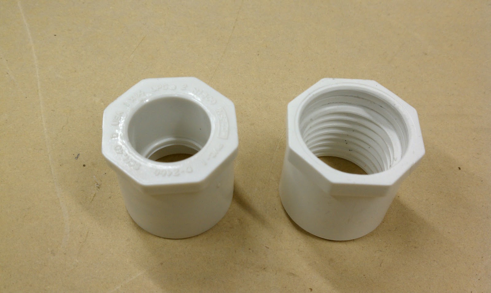 |
| Original and as Modified |
Most documented builds use existing plumbing fittings as they are purchased, and there is no reason not. But for my build I decided to change the shape of the main fitting to be more pleasing to the eye.
 |
| Parts As Purchased |
For my build, I modified the fittings as shown.
 |
| As Modified Not much was done to the Coupler |
 |
| As will be used |
The preliminary dry fit shows how it all should look when (almost) completed.
 |
| Dry Fit The Trigger, Third Bottle and Barrel to be Added |
The Trigger method has not be solidified yet, most documented Launchers use a standard electric underground sprinkler valves, modified for direct Pneumatic action.
This should be a very light Launcher, and maybe used over the shoulder for best aiming. This will be fun to shoot and use. Tess (my Dog) retrieval will make it just that much more enjoyable.
--
Monday, August 15, 2011
Tennis Ball Launcher
Ham Radio is not ALL about Electronics and/or QSO's ?
For the last few days I have been searching and collecting the parts to build a Tennis Ball Launcher, the goal is to Launch lines over the trees around my Shop for several Dipoles.
Previously I had collected Pulleys and Lag Bolts with plans to hire a tree climber to install the supports for an antennas.
But, during Salmoncon (see previous post), Rod - KE7X showed me how easy it is to put lines over very-very tall trees for supports, using a Tennis Ball Launcher. In fact, the Tennis Ball Launched line can be put higher into a tree than possible with a tree climber.
I got-to-have one of these!
A little web research suggests there are many designs and configurations for a Launcher.
The first problem is finding right size Launch Tube, a Tennis Ball is about 2.65 inches in diameter. Standard 2.5 inch Schedule 40 PVC pipe is about (as you might expect) 2.5 inches inside diameter. A Tennis Ball can be forced into this tube, with a ram of some sort. Many designs found on the web use this commonly available size PVC pipe (with a ram), and apparently they work quite well.
But, Rod (and other web users) suggest it is worth finding a length of lesser-available "2.5 inch SDR-21 PVC Pipe", a Tennis Ball fits fuzz tight in this slightly thinner wall pipe. The fittings for this size are readily available as they are are the same as used for normal Schedule 40 PVC pipe. Although 2.5 inch pipe and 2.5 inch fittings are not available at the standard Box Hardware Stores (Lowes).
With a little Googling, I found a local Whole Sale Plumbing Supply house that stocked 2.5 inch SDR-21 pipe in 20 foot lengths, and the price was not bad, at $22.00 per stick. They also had the fittings. I will add a parts list here (that I will use) later.
The next task was to find a valve, the larger the better, but at a reasonable price. There are several types and vendors available from the Box Hardware Stores. The valves are typically used for under ground sprinklers which are power and controlled by a timer. I wanted at least a 1 inch valve. Most newer Launcher designs seem to use one of this size. Rod's design (and other web users) uses two valves in parallel for more air flow, I may try two valves later. Some of the available values are complex and are overkill for a simple launcher. I found a simple One Inch Orbit Valve (#57101) for $12.00, we will see how well it performs.
The next task is to decide on the fill connection, pressure gauge, and release trigger mechanism. The fill connection and Pressure Gauge were found at an Auto Parts store, the gauge is a little bigger then I want but it will do.
For initial trials, I will use the standard electrical connection to the valve for the release. Rob, and most web users modify the valve to allow for simple pneumatic release and therefore not requiring a battery. The valve I purchased appears to operate correctly with just a 9 Volt battery, and yet it is simple enough that can be modified for pneumatic release if necessary.
Most published designs use a PVC pipe with caps for the air reservoir, I found one design, The Trident, that uses plastic coke bottles, which make the Launcher much lighter. I think my initial design I will try this approach. I am drinking the content of the first bottle as I write.
More details will follow !
--
For the last few days I have been searching and collecting the parts to build a Tennis Ball Launcher, the goal is to Launch lines over the trees around my Shop for several Dipoles.
Previously I had collected Pulleys and Lag Bolts with plans to hire a tree climber to install the supports for an antennas.
 |
| Rod Ready to Fire |
I got-to-have one of these!
A little web research suggests there are many designs and configurations for a Launcher.
The first problem is finding right size Launch Tube, a Tennis Ball is about 2.65 inches in diameter. Standard 2.5 inch Schedule 40 PVC pipe is about (as you might expect) 2.5 inches inside diameter. A Tennis Ball can be forced into this tube, with a ram of some sort. Many designs found on the web use this commonly available size PVC pipe (with a ram), and apparently they work quite well.
But, Rod (and other web users) suggest it is worth finding a length of lesser-available "2.5 inch SDR-21 PVC Pipe", a Tennis Ball fits fuzz tight in this slightly thinner wall pipe. The fittings for this size are readily available as they are are the same as used for normal Schedule 40 PVC pipe. Although 2.5 inch pipe and 2.5 inch fittings are not available at the standard Box Hardware Stores (Lowes).
With a little Googling, I found a local Whole Sale Plumbing Supply house that stocked 2.5 inch SDR-21 pipe in 20 foot lengths, and the price was not bad, at $22.00 per stick. They also had the fittings. I will add a parts list here (that I will use) later.
The next task was to find a valve, the larger the better, but at a reasonable price. There are several types and vendors available from the Box Hardware Stores. The valves are typically used for under ground sprinklers which are power and controlled by a timer. I wanted at least a 1 inch valve. Most newer Launcher designs seem to use one of this size. Rod's design (and other web users) uses two valves in parallel for more air flow, I may try two valves later. Some of the available values are complex and are overkill for a simple launcher. I found a simple One Inch Orbit Valve (#57101) for $12.00, we will see how well it performs.
The next task is to decide on the fill connection, pressure gauge, and release trigger mechanism. The fill connection and Pressure Gauge were found at an Auto Parts store, the gauge is a little bigger then I want but it will do.
For initial trials, I will use the standard electrical connection to the valve for the release. Rob, and most web users modify the valve to allow for simple pneumatic release and therefore not requiring a battery. The valve I purchased appears to operate correctly with just a 9 Volt battery, and yet it is simple enough that can be modified for pneumatic release if necessary.
Most published designs use a PVC pipe with caps for the air reservoir, I found one design, The Trident, that uses plastic coke bottles, which make the Launcher much lighter. I think my initial design I will try this approach. I am drinking the content of the first bottle as I write.
More details will follow !
--
Thursday, December 24, 2009
Loop Antenna
A year or so ago, I started experimenting with 30m Loop Antenna.
Not knowing exactly what I was doing I started with Grey PVC Conduit and Electrical Box Fittings. I used two 10 foot sections bent into a circle with a square box fitting at the bottom and a tee pull-box at the top. The loop is about 19 feet in circumference (a little was cut off to remove the bell ends). Bending was done last summer in the hot sun. I have made two of these and have done different experiments on each - and, have learned something new at each revision.


Somewhere I had read that a single loop antenna had a very low impedance feed point 180 deg from the top or from the tuning capacitor. I used 12 AWG as the element inside of the conduit, looping through the conduit from the top, down to the toroid and back up to the top (that was fun!?).


Experientially, I found a 4x2 turn toroid would provide a close match to my 75 ohm feed source, I used my AIM-4170B to check the feed performance. Also, during the experiment I found that 4-47pF cap would resonate the loop at 30m (10.140mHz). With a little tweaking of the toroid turn count and ratio, I should be able to get a low 1:1 SWR.


When I did all of this, I only had QRSS station and Grabber running, I did not have WSPR to make proper antenna comparison measurement. But. it did work well for both QRP QRSS Transmit and Grabber operation.
Recently, I have been reading Joachim's blog, where he describes the DCTL (Distributed Capacitance Twisted Loop) antenna. Well, my antenna looks somewhat like a DCTL antenna, only it has a lump capacitor at the top. I have started thinking I should rewire it with 300 ohm twin lead and driving it with my toroid transformer.
The next experiment, is going to use 300 ohm Twin Lead for the element. My concern is not the actual resonate frequency, only it's feed point behaviour, I can fix the resonate frequency later by change the loop size or a tuning cap.
My goal is to build a loop that is simple and easy, and that will be easy to keep in tune.
UPDATE1:
I have measured the wire length or the inside of the conduit at 5.7m (18.70 feet) and calculated 1.81m (5.95 feet) Diameter.
-
Not knowing exactly what I was doing I started with Grey PVC Conduit and Electrical Box Fittings. I used two 10 foot sections bent into a circle with a square box fitting at the bottom and a tee pull-box at the top. The loop is about 19 feet in circumference (a little was cut off to remove the bell ends). Bending was done last summer in the hot sun. I have made two of these and have done different experiments on each - and, have learned something new at each revision.

Top of the loop Tuning 4-47pF Cap

The Bottom Box, with Toroid Core for Matching
(sorry, my old camera can not take a good photo for here)
Somewhere I had read that a single loop antenna had a very low impedance feed point 180 deg from the top or from the tuning capacitor. I used 12 AWG as the element inside of the conduit, looping through the conduit from the top, down to the toroid and back up to the top (that was fun!?).

Loop Schematic
(Now measured at 18.70 feet Circumference)
(Now measured at 18.70 feet Circumference)

30m Loop As-Built
Experientially, I found a 4x2 turn toroid would provide a close match to my 75 ohm feed source, I used my AIM-4170B to check the feed performance. Also, during the experiment I found that 4-47pF cap would resonate the loop at 30m (10.140mHz). With a little tweaking of the toroid turn count and ratio, I should be able to get a low 1:1 SWR.

With Good SWR - Showing about 1.6:1
Scale = 9.5 to 10.5mHz
Scale = 9.5 to 10.5mHz

A Well Behaved Feed Point, Showing nothing strange over a Wide Range from 2 to 18mHz
(Note: above 20mHz nothing too strange happens)
(Note: above 20mHz nothing too strange happens)
Recently, I have been reading Joachim's blog, where he describes the DCTL (Distributed Capacitance Twisted Loop) antenna. Well, my antenna looks somewhat like a DCTL antenna, only it has a lump capacitor at the top. I have started thinking I should rewire it with 300 ohm twin lead and driving it with my toroid transformer.
The next experiment, is going to use 300 ohm Twin Lead for the element. My concern is not the actual resonate frequency, only it's feed point behaviour, I can fix the resonate frequency later by change the loop size or a tuning cap.
My goal is to build a loop that is simple and easy, and that will be easy to keep in tune.
UPDATE1:
I have measured the wire length or the inside of the conduit at 5.7m (18.70 feet) and calculated 1.81m (5.95 feet) Diameter.
-
Wednesday, December 2, 2009
Catching Up with Ham Radio
The last few days I have been very busy with tedious non-Ham Radio activitives, on this short break from that, I will dump what is in my head.
I put together an external Audio Isolation Transformer for my 30m Grabber Direct Conversion Receiver. This should remove the 60 and 120Hz hum-bars as displayed on the 30m Grabber. The transformer is not exactly a 600 Ohm Audio transformer, but it will work for now.

I also put in a Stereo Jack with the correct wiring so that I can now do away with the previously used adaptor. I made the mistake when building the receiver by not installing a stereo jack in the first place.
The temporary fix if ready, it works on my bench, now all have to do is find time to goto the receiver site and plug it in.
Also, I was reading Joachim's blog, where he describes the DCTL (Distributed Capacitance Twisted Loop) antenna - it is recommended reading. I like loop antennas!, with my new understanding of the DCTL, I may try it.
-
Sunday, November 15, 2009
Finished - Small Trace 5mils 30m QRSS Transmitter
I received in the mail a KID2 Keyer to finish the Small Trace 5mils 30m QRSS Transmitter (see previous post).
This circuit produces 43uW of QRSS FSK power into a 75 ohm load on 10.140080mHz from 9Volts at 4.5ma.
The goals of this experimental project was to:

This transmitter will be installed in the centre insulator of a 30m Dipole (see previous test)
Note: the frequency dose not seem as "hand proximity" stable as other similar circuits that I have produced. I think the lack of stability is due to the very small (5mil) traces used, each small trace contributing a small amount of Inductance to each component and therefore hand proximity capacitance is more determinately effective. More tests are needed?
-
This circuit produces 43uW of QRSS FSK power into a 75 ohm load on 10.140080mHz from 9Volts at 4.5ma.
The goals of this experimental project was to:
- build the smallest PCB that I could produce using my current Home Brew techniques
- use all SMT parts (except Crystal, Battery and Keyer)
- use smaller than industry standard trace sizes (used 5mils)
- use no more parts than necessary
- build a real and useful working circuit

This transmitter will be installed in the centre insulator of a 30m Dipole (see previous test)
Note: the frequency dose not seem as "hand proximity" stable as other similar circuits that I have produced. I think the lack of stability is due to the very small (5mil) traces used, each small trace contributing a small amount of Inductance to each component and therefore hand proximity capacitance is more determinately effective. More tests are needed?
-
Wednesday, November 4, 2009
A Balloon QRSS Idea
My micro watt QRSS Transmitter is so small, light and inexpensive, I should "Fly it on a Balloon"?
See previous post.
See previous post.
- At 25K feet, I wonder what range could be expected of 43uW QRSS transmitter?
- I wonder what the Rules/Regs are regarding an experiment like this?
- I wonder if I could get special permission from the FCC to have an MEPT transmitter out of my reach/control - until the battery runs out?
- Just wondering, does the FCC have jurisdiction over 43uW Transmitters?
- A centre feed 1.5 wave 30m Antenna could be the trailing support.
- I need to do some more checking.
- Would anyone like to join me on this adventure?
Thursday, October 22, 2009
Unsuccessful QRSS Online
The other day I turned off my WSPR, Home QRSS Grabber and DigiPan receive programs, and installed my small QRSS Centre Dipole Transmitter. The System ran for about 30 hours, But Grabber spots were not reported, not even my own remote grabber which is about 8 miles away.
I do not think the 43uw (as measure on an RF Test Set) into a dipole at 15 feet AGL is enough for DX and the ground wave can not go the distance to my grabber.

The Transmitter is installed via clip leads into the Centre Insulator on a 30 meter Dipole.

Planned improvements include more power (qrp QRO), maybe up to a few milli-watts. I have some 2n7002 which will work great for a PA, at the expense of battery life. Just another project to finish - Don't ya' just love it!
-
I do not think the 43uw (as measure on an RF Test Set) into a dipole at 15 feet AGL is enough for DX and the ground wave can not go the distance to my grabber.

Centre Dipole Insulator QRSS Transmitter
The Transmitter is installed via clip leads into the Centre Insulator on a 30 meter Dipole.

The Transmitter's Working QTH
Planned improvements include more power (qrp QRO), maybe up to a few milli-watts. I have some 2n7002 which will work great for a PA, at the expense of battery life. Just another project to finish - Don't ya' just love it!
-
Sunday, October 11, 2009
A new 30m Vertical - Installed
My new 30m Vertical is Installed at the new Data Centre and the Direct Conversion Receiver (SA602) is providing QRSS Grabber Images to the WEB - so far, it works like a Champ! (fingers crossed).

The Grabber Web address is:
I hope the is NOT a premature announcement of a successful move of my Seattle QRSS Grabber with 24x7 Availability. After making several similar announcements, over the last 6 months, on failed attempts, I think I got all the right pieces in place this time.
I would have NOT believed that it was going to take this long to relocate my grabber and have it in operation.
The new Antenna, Grabber and Data Centre is about 7 miles way from my QTH, which means that I can now transmit PSK or other, without de-sensing or overloading the Grabber Receiver.
-

Installed and working!!
With an under ground feed
Radials will be installed later, before sod is installed
With an under ground feed
Radials will be installed later, before sod is installed
The Grabber Web address is:
I hope the is NOT a premature announcement of a successful move of my Seattle QRSS Grabber with 24x7 Availability. After making several similar announcements, over the last 6 months, on failed attempts, I think I got all the right pieces in place this time.
I would have NOT believed that it was going to take this long to relocate my grabber and have it in operation.
The new Antenna, Grabber and Data Centre is about 7 miles way from my QTH, which means that I can now transmit PSK or other, without de-sensing or overloading the Grabber Receiver.
-
Saturday, October 10, 2009
A new 30m Vertical - Base
I finished the 30m Vertical Base, it is complete, and ready for installation. The upper aluminium sections are cut and split, also ready for installation. I will lub the slip joints with "GB OX-GARD" even though oxidation is not a problem away from salt water of Puget Sound.
This antenna will be used for QRSS, WSPR and PSK on 30 meters.

 I guessed at the value of a bleed resistor 2.2K Ohms. It is what I had, greater than 10 time 75 Ohms. The end of the aluminium sections are open so they do not collect water, which was a problem with my old 4-BTV base.
 The copper strap will be in contact with the support pipe which is driven into the ground. Radials will be attached on the bolts below.
This antenna will be used for QRSS, WSPR and PSK on 30 meters.

Ready to be mounted, the upper aluminium sections slip into this base and clamp at splits at the top of the first short base section.
 I guessed at the value of a bleed resistor 2.2K Ohms. It is what I had, greater than 10 time 75 Ohms. The end of the aluminium sections are open so they do not collect water, which was a problem with my old 4-BTV base.
  The copper strap will be in contact with the support pipe which is driven into the ground. Radials will be attached on the bolts below.
 In hind sight, it may have been less expensive to find a commercial 20 or 40 meter antenna and make modifications, but I do not know of such an antenna. Maybe I should have just used a wire strung in a tree!?
But, It was still a good enjoyable Shop Project!
-
Thursday, October 8, 2009
A new 30m Vertical - Insulators
I have started machining the Hard Plastic Insulators for the antenna mounting bracket.


Centre hole to fit largest antenna tube
Ian, my Great Nephew (9yr) is staying with me for a few days, he likes to work in my Shop on small projects. But, I do not like him to be close to the machines while I am intently working. So, I gave him a project to keep him busy - I thought, it would take him about two hours to put a plastic Transmission Kit project together. NOT! - he was done in about 30 minutes.

Parts laid out, with instructions at the ready

He is going to be a great Engineer someday!
Back to my Insulator Project

Ready to start turning the outside

Almost finished machining the first Insulator
This is a just a trial fit.
Ian's Finished Project

Ian was finished long before I was finished for the day!
After his project was finished, he wanted to just stand and watch the turning process on the Insulators.
It is a real joy to have someone, so young, so interested, and so intent on Shop projects.
Unfortunately Ian will not have a chance to get much Shop training in school - as I once had in my high school Shop classes. Local schools "don't do Shop" any longer. Looking back now, if it had not been for my Shop classes - I would have been just another LOST kid in a big school!
Unfortunately Ian will not have a chance to get much Shop training in school - as I once had in my high school Shop classes. Local schools "don't do Shop" any longer. Looking back now, if it had not been for my Shop classes - I would have been just another LOST kid in a big school!
-
Subscribe to:
Posts (Atom)