Showing posts with label Propeller. Show all posts

Thursday, March 21, 2013

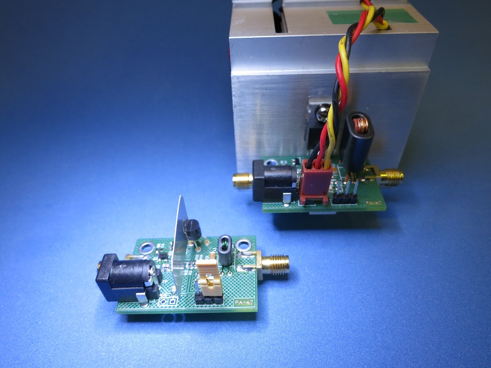
RPi as a WSPR Beacon with PA47


UPDATE:
Sorry,  this did NOT work as expected, the Wsprrypi code is still being developed. The second fork of the program is available. The RF output of the of the RPi is less noisy if the DC supply is from a well filtered source.


I have previously built my Homebrew PA47 Power Amplifier for a Propeller Microprocessor Beacons (see previous selected posts). The Propeller provides 12mW to drive the PA.

The Raspberry Pi provides about the same output power via the Dan Ankers Wsprrypi program. Therefore. it was a simple mater of connecting to the correct pins on the RPi GPIO Connector to give it a try. Thanks Dan !

Here is my initial lash up, with just a Low Pass Filter (LPF).
RPi WSPR Beacon with LPF
Measure Output into 50 Ohms =  5dbm
Here is the RPi and the PA47, with input and output LPFs attached.

With the two low pass filters, the measured output is 9.4 V PP at a 50 ohm load, or 220mW, which is 23.4dbm. The Dan's WSPR program uses only about 3% of the CPU.


I have plans to modify Dan's Wsprrypi program to include other beacon modes (e.g., QRSS) similar to those that I have used with the Propeller Processor.

FYI, This my complete family of experimental PA47 Amplifiers.
My PA47 Family
Max Power - 1w, 5w and 15w

On the air, WSPR Received Reports will be added here.


-- Home Page: https://WA0UWH.blogspot.com

Thursday, January 31, 2013

PA47 Now Ready for On The Air Tests

Thus far I have NOT connected my PA47 Amplifier to an antenna, because I was not sure of it output harmonic content (see previous posts).

Last night at our monthly P&C group meeting, Wayne - NB6M presented a demonstration of his new DSA815 Rigol Spectrum Analyzer with one of his oscillators and the effects of a output filter devices. His filter completely eliminated (down into the noise floor) any harmonic content.

As a second example and demonstration, I provided the PA47 Amplifier and a LowPass filter. A 50 Ohm load and 40db tap was used to reduce the input to the Analyzer. Actually, both the 1 Watt and the 15 Watt versions of the PA47 were checked, the results were about the same.
The 1 Watt and 15 Watt Version of PA47
The output filter that I used, is a simple Chebyshev 5 Pole Filter (as previously posted).

30m LowPass Filter as Designed with LtSpice
The filter was originally designed via an Online Filter Design program, and then available multiple 330pF 1206 SMD caps were used to obtain the nearest values, 3 caps for each end, and 4 for the center. The cores were wound as necessary by measuring the results on an AADE LC meter.

30m LowPass Filter as Implemented
The Results

Wayne declared the PA47 fit for Amateur Radio Service. The second harmonic was down 51db and the third was down 67db from the fundamental.
PA47 Connected to
DSA815 Rigol Spectrum Analyzer
I will soon connect the 1 Watt version of the PA47 to an Antenna, and use if for QRSS Beacon Service on 10.140050MHz (+-50).

--

Wednesday, December 26, 2012

Destructive Testing of PA-47

Late last night before leaving my Shop, I inadvertently put a 12.6 Volt supply plug onto the 1 Watt PA, which was designed for only 9 Volts (see previous post). The results was a toasted 2N7000, but that is NOT really a problem, as I have replacement parts (and boards).
PA-47-1 and PS-47-5

Later in bed, and while trying to fall asleep, I got to thinking; Why not do some Deliberate Destructive Testing while recording circuit parameters? I could think of several scenarios that would be fun to try.

And besides, how often do you get to deliberately abuse two of your favorite RF Power Amplifiers?

Some Abuse Comes to Mind:
  • Put an over-voltage on the supply connector (similar to the mistake above).
  • Run the PA at the over-voltage condition while cooling the FET with Freon.
  • Create maximum VSWR at the PA output with a shorted and open coax (this may have to wait for another day) 

For the tests, several FETs were prepped from randomly selected Volunteers. Each was outfitted with an attached HeatSink. The HeatSink is a 1 inch square piece aluminium flashing, super-glued to the FET.
Preparation for Expected Failures
Initial Normal Use - Base Line Tests

Input to the amplifiers is provided by my Propeller microprocessor system, which supplies about 12mWatts into the amps (see previous posts).

PA-47-1, A one Watt PA, with Normal DC Supply Voltage
  • Power Off - HeatSink at 75.7F
  • 9.1 Volts DC, RF input Off, 41 ma, HeatSink at 82.4F
  • 8.8 Volts DC, RF input On, 250 ma, HeatSink at 103.6F => 20 Volts PP at 50 Ohm Load => 1 Watt
PA-47-5, A Five Watt PA, with Normal DC Supply Voltage
  • Power Off - HeatSink at 73.4F
  • Fan Off, 12.1 Volts DC, RF input Off, 90 ma, HeatSink at 82.9F
  • Fan On, 12.1 Volts DC, RF input Off, 270 ma, HeatSink at 73.8F
  • Fan On, 11.5 Volts DC, RF input On, 1170 ma, HeatSink at 102.9F => 42 Volts PP at 50 Ohm Load => 4.4 Watts

PA Input (lower) and Output (upper)
Output is 4.4 Watts
5 Volts Per Div

Destructive Tests

PA-47-1, A one Watt PA, with Over Voltage Supply - Rated at 12.5V at 1200 ma
  • Power Off - HeatSink at 75.7F
  • 12.1 Volts DC, RF input Off, 80 ma, HeatSink at 84,9F
  • 11.8 Volts DC, RF input On, 710 ma, HeatSink at -25.3F with Freon => 30 Volts PP at 50 Ohm Load
  • 11.8 Volts DC, RF input On, 520 ma, HeatSink at 148.6F without Freon => 25 Volts PP at 50 Ohm Load
  • Output Transformer was Hot to touch.
  • Only the FET Failed 40 seconds after Freon was removal, afterwards maintained 145F while power was applied - FET was toast!

PA-47-5, A five Watt PA, with Over Voltage Supply - Rated at 31.5V at 3170ma
  • Power Off - HeatSink at 73.4F
  • Fan connected to a separate 12 Volts DC Supply
  • Fan On, 30.19 Volts DC, RF input Off - The FET and the two drive (Sziklai) transistors Failed within 3 seconds of DC voltage being applied.
End of Destructive Testing

The Dead Soldiers

Several FETs were used to collect this data, only a condensed synopsis is provided above.

Conclusion

The PA-47 Circuit boards survived much better than I would have had imagined, components failed long before the PCB traces. For Higher Power PA's more design aspects need to be understood and considered.

The two PA circuits have be restored to there former condition, awaiting further tests or use.


Destructive Testing - Epilogue :-)

For the above described Destructive Tests, all intentionally destroyed FETs were randomly selected Volunteers (RIP). They are well preserved and available for additional photos and future forensic examinations.

Although mildly inconvenienced, no Electrons were Captured, Created or Destroyed as part of these experiments, they were ALL returned to their point of origin.

Almost all (well, maybe some) of the released Magic Blue Smoke was captured or contained for return to the part manufacture, if desired.

All transferred RF energy was absorbed by the 50 Ohm Load, most of it was emitted as therms and dissipated into the surrounding area. Only a small fraction of RF energy was transferred to a local Receiver where is was used to monitor the testing progress.

Only Ozone Depletion-Free R-134 Freon was used for the cryogenics phase of these tests.

With some microscopic surgery, all Causalities were fixed, repaired, or replaced. Both boards have fully recovered and will be returned to original service.

All of this was in the name of; Science, Ham Radio, and/or just plain FUN :-)

--

Sunday, December 23, 2012

PA-47 At Only 1 Watt

Original PA-47
with Large Heat Sink, 
Matching Transformer
and FET IRF510
In keeping with my goal of making my Homebrew projects as small as my abilities allow and using the same previously created PCB board (see previous post on my PA-47 Power Amplifier)

I have reduced the size of the output matching transformer and changed the output FET from a IRF510 (TO-220) to a 2N7000 (TO-92).

New PA-47  Running at
1 Watt Output

Knowing that the 2N7000 would not produce the same 4.7 Watts of the replaced IRF510 with its large heat sink, I planned to reduce the supply voltage; from 12.6 Volt down to 9 Volts, and reduce the size and turns ratio of the matching transformer form 1:3 to 1:2.


New Replacement Parts
of the Original PA-47
are the 2N7000 and 

Smaller Matching Transformer

Initial test produced 1 Watt RF output, and a Very Hot 2N7000 FET. A small 3/4 inch sq piece of aluminum flashing was super-glued to the FET which solved the heat build-up problem. Just in case, I also installed a pin socket for each leg of the FET (which means I can easily replace the FET, if I inadvertently cause it to release its Magic Blue Smoke :-).

For this first test, the DC input was 8.5 Volts (not a very fresh battery set) at 360 mAmps: or 3.06 Watts DC Input, which suggests the PA at only about 32% efficient (more work is maybe needed to increase this). The standby current (no RF input) is about 13 mAmps, and most of that is used to drive the green Power-On LED.

30 Meter Low Pass Filter

Without the FAN and Large Heatsink that was used in the initial PA-47, this PA is silent.

Like the original PA-47 an outboard Low Pass Filter is necessary and was used for this experiment.


TR Relay Mounted Under the PCB

The yellow-tag jumper on the header turns on the TR Relay, which is mounted on the under side of the PCB. Normally transmitter control from the exciter would be connected to this header.

The RF voltage measured at the 50 Ohm Load via the scope: 20 Volts PP, (20/2*.707)^2/50 => 1 Watt, or as per the web  RF calculator.

This smaller and lower power PA will be perfect for my ongoing Propeller 30 Meter Beacon efforts.

After I correct the PCB layout (see previous discovered errors),  and if there is interest, I may make the PA-47  board available, or as a complete Kit (but, as a board or kit, this would not be suited for first time builders, nor a builder without a Microscope).

The Exciter (Driver)
The Exciter
Outputs 12 mWatts

For this experiments and as explained previously, I used my Propeller Transmitter as the exciter which provides 12 mWatts of drive. The Propeller is the second board in the stack.

--

Sunday, December 16, 2012

PA-47 - A QRP KiloWatt

I have not posted anything for the last few weeks, I have been a little bummed out.  I started work on an interesting Project, which is a "QRP KiloWatt", a 5 Watt Amplifier. It will be used with my Propeller Beacon Project (see many previous posts) and maybe my other QRP projects.

Sziklai Pair
What renewed my interest in building yet another PA, was a new (new to me) configuration of transistors - called a "Sziklai Pair", or sometimes referred to as a "Complementary Darlington". The configuration is actually quite old, and was invented by George C Sziklai  (pronounced as: "SICK-LIE", which is the best guess as per the web). I had not seen or used the configuration before.

To me, the interesting spec is that the Sziklai Pair can produce nearly Rail-to-Rail output voltage - which is exactly what is needed for a FET PA driver. FET PA's require high signal voltages (i.e., +6 or 7 volts to drive the gate) which is much more than the typical 0.6 volts for a normal transistor. Transformers can be used to produce the high drive voltages for FET PA's. But, I did not want to do that, especially if two simple transistors can do the task. I have built PAs before and always had messy drive circuits and problems.

I configured my planned Sziklai Pair Driver and FET circuit within LtSpice. It took a while to get the configuration and front-end bias right for my desired "class C" operation. But in the end, it is much simpler than I had imagined. Resulting in a circuit with very few components. LtSpice suggested I should get about 4.7 Watts at 10.140MHz from 12.6V DC when driven from my Propeller (Prop) Beacon, The Prop only provides about 2.5 P-P Volts at its output pin (or only about 12 mWatts drive).

Excitedly, I transferred the LtSpice configuration into DipTrace Schematic Capture, and from there created a DipTrace PCB layout. The circuit includes; SOT-23 2N3904 and 2N2906 for the Sziklai Pair, a IRF510 for the PA (standing up to mount to a heat sink) and a TR Relay and its support circuit. As usual, I wanted the circuit board to be as small as my abilities allow. The PCB was going to be only 1.5 x 1.0 inches, using SOT's and mostly 0603 parts.

While designing the circuit, I noticed that I had used mostly "47" valued parts, for example 4.7K resistors and 47nF capacitors. And, therefore I decided to name my new QRP KiloWatt - the "PA-47". Just for fun, and with very little work, I was able to convert all parts to 47 values. Besides, LtSpice said it would produce about 4.7 Watts - so what else could I name it?!!

The circuit was so simple I decided NOT to try to breadboard it, I just quickly pressed the DipTrace button and ordered the PCB's (that is way too easy).

For about a week and half, I waited for the PCB's to return from the Manufacture.

PA-47 - PCBs as Received
PA-47 - PCB Under the Microscope
Finally, the PCB's arrived, I excitedly loaded a board. But - DANG!! - I noticed I had used the wrong SOT foot print for the two Sziklai Pair transistors!! Maybe I pressed the DipTrace Order button too soon (the button is just too easy and handy). The two driver transistor's Emitter and Bases were exchanged on the PCB - DARN, DARN and DANG!
2N3904 SOT-23
as  MMBT3904

OK, now what, . . . . if I turn the transistors up-side-down, "dead bug style", the PCB foot print would work. All I had to do was bend the legs up and then try to solder the SOT transistors up-side-down on to the PCB. I notices the leads almost broke off when bending them back that far. I planned to fill the little crack with solder as part of the installation process, it would only require a slightly larger glob  of solder on the pin (actually the glob of solder is about the size of a flyspeck and can only be seen under the Microscope).


For the initial tests, I would not install the parts for the TR Relay Circuit, as it was not really necessary (I just shorted two pairs of the pads together, as if the Relay was always on).

PA-47 - Mounted to a CPU HeatSink
Output Matching Transformer and Connector
on the Right Side
PA-47 - DC Power and RF Input Connector
on the Left Side
I connected the Propeller Project as the Exciter, a Low Pass Filter, the 50 Ohm Dummy Load, and the 12.6 Volt supply to the PA, the Fan came on (a good sign)!. The Propeller was outputting its 2.2 Volts into the PA input. . . . . But nothing was coming out of the PA, - more Dang!

I spent the next several hours trying to figure out the circuit or problem. Remember is a NEW untried circuit, and there is a chance it would NOT work at all. After spending more time trying to make it work. I decided, maybe "I Should Have" breadboarded the circuit first!

So, I started loading a fresh breadboard with components. With still more time (several hours) I still could not get anything to work as expected on either circuit.

The Bench
Dishearted - I gave up - left the shop "without" putting away my tools and cleaning up (I normally always clean up before leaving).

Bummer!!

Several days have past (about a week), it is now Sunday and I am planing to go to Jack's Homebrew Club evening meeting on Tuesday, and the following night I am going to the pQRP monthly meeting. I decided to clean-up the PA (to remove excess solder flux) to make it "look good", and take it to the two meetings, to show my epic FAILURE of a nice idea for the PA.

While cleaning the circuit board, I noticed one of the legs of the (necessarily) "dead bug" mounted transistors did NOT appear to be soldered (with filets) to its pad, it appeared to have just a glob (flyspeck) of solder on the bent leg. This was the drive transistor for the output power FET, maybe it was not actually soldered down!!

For me, it is actually quite difficult to see a single SOT-23 pad without a Microscope.

Under the Microscope I could see it only had flux between the pin and pad!! I heated the soldering iron, fixed the joint, re-connected the Propeller Beacon Exciter, the output Low Pass Filter, the 50 Ohm Dummy Load, and the 12.6 Volt supply, . . .

WOW!, I observed 43 Volts PP at the load. That is; (43/2*.707)^2/50 = 4.7WATTS - YES!!!!!

Which is a gain of 25.93dB.

The PA-47 Curcuit with a Sziklai Pair Driver works!!

I installed the rest of the TR circuit and Relay on the under side of the PCB, but - DANG! The relay would not work! Now what??

After several hours, I discovered that I had attached the Relay Coil to the opposite pins on the Library PCB pads within DipTrace, the Relay is polarity sensitive. Like the drive transistors I had jury-rig the Relay by cross wiring the coil under it to make it work (the fix can not be see in the photo).

After cross-wiring the coil pins and re-installing the Relay - All worked as expected :-)
PA-47 - With TR Circuit and Relay Installed
Regardless of Success or my Failures, Tess is always watching, to make sure everything is being done right! She was not involved with the PA design or PCB layout, but some how she must have missed the poor solder joint!! (actually, . . . she is watching her ball that I placed on the bench :-). If I had her concentration (and other admiral attributes), I may have NOT missed the above critical project details :-))))

Tess - Doing Her Job,
Production, Test, and Final Inspection
I am , . . . ah, . . we are NOW both Happy Campers!

. . . . . Tess has her Ball, and I have my PA!

I will later post more PA-47 Project details. More testing, and more work is needed to install angle brackets to support the PCB.


UPDATE:

Increasing the DC supply of up to 14.2 Volts (via a heavy duty Lead Acid Battery on a Charger), I got 60 Volts PP at the 50 Ohm Load, (60/2*.707)^2/50 = 9.0 WATTS- Nice!!

Note to self:
A Fan control via the TR circuit or HeatSink Temp would be useful, it would save some power and would be quieter.

UPDATE:

Here is the PA-47 running on Jack's Bench at his Homebrew Club meeting, the photo was taken by Jack and who suggested this photo would make a great (complex) puzzle picture :-)
PA-47 Running on Jack's Bench

--

Monday, July 23, 2012

TCVCXO PCBs Received

I just received another set of boards from OshPark.com.

This time they are my corrected TCVCXO boards. The board will provide a Temperature Compensated, Processor I2C Corrected, 10MHz Master Clock for the Propeller Microcontroller (see previous post).

Top Side
Back Side
This board is 0.34 x 0.5 inches with 0603 components. If you click on the microscope photos above, the resulting image will be about 400 times actual size.

 I should have it loaded with parts within the next few days.

--

A Friends Voice From the Past

A voice heard from 45 years ago.

Saturday I was reprogramming my Prop Receiver with new User Interface (UI) Code. The previous UI code did not provide an intuitive controls for the BFO and VFO Frequencies with the two knobs that are available. It had previously been a rush-job, just to have something to demonstrate as a working receiver at Salmoncon (which was the previous weekend).

Prop Receiver on the Left

Now, to test and try the new UI code, I connected the Prop Receiver to an Antenna, a 250 foot long wire that I previously posted a blog. For the test I programmed the default Frequency to 20 meters. With a little twisting of knobs I found the sweet spot for the BFO and was tuning across the band. I heard several stations on CW, and then higher up the band on SSB. I tuned across a signal and recognized a very distinctive friends voice from my past, of 45 years ago, Randy - KH6IB.

I switch the antenna over to my IC-730 and tuned up on near the Frequency that I thought was where I heard Randy on the Prop Receiver. My Prop Receiver Frequency was un-calibrated and therefore I had to do a little searching on the IC-730.  But on 14.227MHz his distinctive voice was heard again. I sent BREAK and waited for his QSO to end. Randy asked for the Breakers, I jumped in with my call - "Whiskey Alpha Zero Uniform Whiskey Hotel". Randy came back with, "the Whiskey station please try again". We made contact, and had a short reminiscing QSO before the band went south. This was my first real on-the-air QSO with Randy.

Actually, Several years ago, Randy and I chatted on EchoLink.

In 1967, while in the Navy, Randy and I were attending the Precision Measurement Equipment Laboratory (PMEL) school at Lowry Air Force Base near Denver CO. I think Randy was a little ahead of me in the six month training schedule, but we meet because of his Ham Radio. A few weeks earlier his Mother had sent him his SB-101 transceiver to use in his barracks. Being a previous Novice, I gravitated to the sound of CW and SSB coming from his room. We spent the rest of our tour/training time at Lowery; walking to-and-from the chow hall and class, chatting about Ham Radio, and his race cars. After graduation and leaving Lowry, I was sent to the East Coast to a Submarine Tender and I think Randy was sent to the West Coast and Vet Nam - I never saw Randy again.

Here I am Aboard The Submarine Tender
 H. W. Gilmore AS-16
1968
So for me, Ham Radio has again brought a voice and a friend from the past.

Oh, The Prop Receiver seems to work well, even though I have not checked the receiver sensitivity yet. And, I have not tried to energize the Band Switch Relay and then try the low bands and lower sideband (below the 11MHz IF).

--

Tuesday, July 10, 2012

Prop Controlled Receiver - Success

In the past I have blogged about the QRSS, WSPR, and OPERA Beacons that I have created with the Propeller Microprocessor (Prop). The Processor generates the RF signal that is passed through a LowPass Filter to remove Harmonic, and then connected to an Antenna. For some experiments a Homebrew Power amplifier was used to increase the processor generated RF signal from 7 milliwatts to 150 milliwatts. I have received many reports (or Spots) from many stations around the world. I think the farthest was from Australia at about 12,000 miles. I consider my Propeller Beacon a fun and very successful project.

And Now,  . . .

I have been playing with the idea and trying to receive signals with the Propeller. A simple direct conversion receiver using a SA612 mixer would require a Local Oscillator at the received frequency. The Propeller can generate RF frequencies from; 0 to 128MHz, with an amplitude of about 3Volts Peak-to-Peak. Which is a little more than needed by the SA612, but it can be attenuated with simple resisters if needed.

My original plan was to construct a simple direct conversion receiver daughter board for the Prop. But, Jeff - KO7M pointed out that the N3ZI Double Conversion Receiver using two of the same SA612 chips, was available as a kit (this was actually several months ago). I put the kit on order, and it has been setting around waiting for my User Interface (UI) project to be completed (or at least working). The receiver kit needs two RF signals, one for the VFO and one for the BFO (about 11.055MHz). The BFO is normally supplied by a Crystal. I plan to replace the BFO Crystal with another RF signal from the Prop.

For the High Band (above IF) and Upper Side Band, the injected frequency is the BFO frequency (IF) plus the intended (displayed) receive frequency. For example, for USB: the VFO = BFO + Received Freq, for LSB: VFO = BFO - Received Freq.

For the Low Band (below IF) and Lower Side Band, the injected frequency is the BFO frequency (IF) minus the intended (displayed) receive frequency. For example, for USB: VFO = BFO - Received Freq, for LSB: the VFO = BFO + Received Freq. (I think that is correct?)

Obvious the VFO should be adjustable so the receiver can be tuned to the desired received frequency. But, maybe not obvious, is that small adjustment of the BFO can be used to adjust the band width of the received signal. In both cases a handy way of adjusting either or both frequencies is necessary. And that is where my UI comes in, it has knobs and buttons that can be programmed to control two Prop RF signals which will be supplied to the receiver.

Note: Sadly, I think the N3ZI Receiver Kit is no longer available.

Prop Controlled Receiver - Left
Prop Transmitter - Right
Today's Success !!

I have one Prop running ko7m's Keyer Program and another controlling the double conversion receiver. The test distant between the transmitter and receiver was only about 12 feet, but it works !

With the receiver connected to an antenna, I have received other signals with this set up; WWV and other Amateur stations.

The Receiver is mounted under the Prop on the left, the two SMA coax cables connect the VFO and BFO. Two of the corner holes of the receiver match the hole pattern of the Prop board (nice). The Keyer Transmitter is on the Right.

This weekend at Salmoncon, Jeff and I will demonstrate some of our Prop projects. Maybe, we will have time attempt to do real QRP DX'ing with our Props.

Many more experiments and improvements are planned.

For now, . . . it all just, fun and games, with the Prop !!

--

Wednesday, July 4, 2012

Under the Microscope

Cutting Under the Microscope
I think I have past a personal milestone on my forever quest to build ever smaller projects.

I noted the passing, when I realized it was much easier to cut-out my paper models of a new small PCB under the microscope.

The scissors look like huge shears under the microscope.

This new TCVCXO board is required due to pin mounting hole miss-alignment (my error) on the previous PCB. This time I am using the cut-out TO MAKE SURE it is correct.

Alignment Conformation
A straight pin pushed through the holes ensure hole alignment. The fifth pin is at an odd, non-standard location and has caused me trouble.

Note: for scaling, the protoboard holes are 1.0mm in diameter and on 1/10 inch centers.

The paper cut-out now confirms the new PCB layout

This paper image is the same that I would use to create a Homebrew Toner Transfer PCB (if that was my goal) but for this board I will be using the service of OshPark.com (again).

The five Crystal Pin Sockets (see previous post) are installed and ready to receive pins from the new TCVCXO board.

Pin-Sockets Installed
I took this pin-move opportunity to shrink the TCVCXO board even smaller, it is now only 0.34 X 0.5 inches, which is smaller by about 25 percent.

I do enjoy making projects as small as my abilities and eyes allow.

The two bottom Pin Sockets supply I2C Signals (jumper wires will be added on the back side), the next two Pin Sockets supply GND and 3.3Volts (the Propeller board already has them connect to VDD and VSS), and then the new TCVCXO board supplies its 10MHz output to the single Pin Socket (upper Center) to the Processor Crystal Input. The Processor multiplies its input by eight, to supply its internal required 80MHz clock frequency.

The sixth pin socket shown in the photo (upper right) is one of the the standard 5MHz Crystal sockets, which will not be used with the 10MHz TCVCXO board installed.

This is a proven circuit, I am just trying to get the final implementation right.

--

Monday, June 18, 2012

TCVCXO PCB Received from OshPark

I received my TCVCXO PCB back from OshPark.com (see previous post) This board with be used with the Parallax Propeller as a Crystal replacement. It is a Tiny board, only 0.365 x 0.650 inches (0.062 inch material). The PCB layout for this project was created using the DipTrace Schematic Capture and PCB Editor.

I attempted to take photos with the same origination as the previously posted 3D models (which proved to be more difficult than I thought :-) Here is the results. More "Light" is needed - I think I would like to build a "photo shoot light box" for taking future photos.

Top Side

Bottom Side


Now it is time to load and test this thing.


UPDATE:
OK, now I am envious, I just read Dave Richards -AA7EE,  post of his gorgeous Photos of the Air Variable Capacitor. Thanks Dave, I learned a few things!

UPDATE:
Dang! . . . I got the pin hole alignment wrong, I need to re-layout the board, again  :-(

--

Sunday, June 10, 2012

Prop UI Progress

It has been a grueling 18 days since my last post. The Propeller UI Board that I have been working on has provided some real challenges. All of the UI Board peripherals on wired to the same I2C Bus. Which means my standard method of debugging the code via a working a Display was not available. The Bus Pirate and a new VGA Display was necessary, which had to be configured which added to a already steep learning curve.

UI Board Installed on the Prop ProtoBoard
Coordinating and developing the Objects for the six UI peripheral was a challenge The task was a little easier thanks to Jeff - KO7M, who helped with the I2C Bus to Parallel Expander Code, and the necessary modification to his I2C LCD Driver.

Currently ALL six UI peripherals, which are on the same I2C Bus, are working in concert with each other without perceivable delays for; the two Rotary Encoders, four Push Buttons, eight LEDs, a Realtime Clock (RTC), and the LCD Display. Also there are the Sound (beeper) and the three I2C POTs that control the LCD Backlight Brightness, LCD Contrast, and Sound Volume - all working seamlessly together.

One of the Software Driver Goals is make moving the Programmed Display from LCD to VGA (and back) without difficultly, other than the obvious which are the Number of Lines and Number of Characters Per Line.

Note: my new I2C Huff-n-Puff board (see previous blog) will also be added to that same I2C Bus (external to the UI).

I had to learn a few new Propeller SPIN tricks to make it all work. Specifically how to coordinate and use "Locks" for Objects and COGs.

Only a few modifications were necessary to the UI PCB. I have already started the re-design with modifications for the next PCB. I will be adding more Pull-ups, and 0-Ohm Jumpers to make separation of circuits easier for future development and debugging.

I have several ideas and better organization of the current code, but that will wait for another day.

It has been a lot of fun. Now on to some projects that will use the Prop UI Board.

First, on the list to port are; my QRSS and WSPR Beacons, Jeff's Keyer, the Huff-n-Puff Freq Standard, and several other Prop Projects that are planned to use the new UI.


--

Friday, May 25, 2012

UI Project Update

Readers of this blog know that I have a Propeller UI Project in progress. The custom board that I created for that has been received and loaded with parts. Some simple parts of the board appear to function as can be seen, tested, and exercised with a clip on Bus Pirate. That is, the Real Time Clock (RTC) and the LED driver seem to work as expected.

The major elements of the board; which include the LCD Display and Knobs, have NOT been tested yet. Their control is complex enough that it will be necessary to tested them in conjunction with the Propeller processor. The eight interface wires for the connector have been installed on the Prop board.

Normally testing a new peripheral device is not difficult, but when the test and debugging involves the Display, which is used to Display the test results, it is problematic. It is a classic "Chicken and the Egg" problem.

To solve this dilemma, I am waiting for an ordered KVM connector for the Propeller (which should be here today). The KVM connector will allow the Prop to be connected to a dedicated VGA Monitor for display of debug information without the need of the LCD or Knobs.

Actually, I have been a little lax here, I could have used the USB TTY connection to do debug and testing, but in my Ubuntu Workstation environment using a single interface path for both; Prop Programming, and Displaying debug information, is a pain. Therefore I have been waiting for the KVM. And, I have also been diverted off to other projects and responsibilities.

My goal is to have UI working for Show-n-Tell at the next pQRP P&C meeting.

--

Tuesday, May 22, 2012

New TCVCXO PCB with OnBoard I2C Control

With the very good results of the TCVCXO Propeller Master Clock experiments (see previous post), I decided to rebuild the PCB to include the I2C Pot and Filter Caps on the same board. This is the expected results when produced:
Top
Bottom
Note: This board is very small, it is only 0.365 x 0.650 inches. The above images are local screen prints of DipTrace 3D output.

I often use Homebrew Tone Transfer Method to produce my PCB's, but I use DorkBotPBX to produce my manufactured boards.

Laen (the owner of DorkBotPBX PCB) is now using a new web site: OshPark.com and using a new interactive process for submitting PCP designs. The new web site was introduced at the Bay Area Maker Faire 2012.

The site accepts Eagle and Generic ZIP'd Gerbers (as exported from DipTrace). The interactive process receives the ZIP'd file and renders the design, showing the individual layers and what the board will look like when finished (in Laen's standard Purple color). Very Cool.

The price is the same, $5.00 per square inch for a set of three, two sided boards.

Check it out at: OshPark.com

--

Wednesday, May 16, 2012

The Results Are In

 . . . . I think.

Last night I took my Huff-n-Puff driven Master Clock for the Propeller Microprocessor to Jack's Homebrew Amateur Radio Meeting, to compare it with his GPS Disciplined 10MHz Standard (see previous post).

Jack had problem getting his equipment ready, the 10MHz Standard was questionable and he had not built the Phase Comparator/Detector as of yet. We proceeded anyway to look at his and my 10MHz signal on his Dual Trace Scope.

I had previously miss-adjusted my TCVCXO to a slightly lower frequency, so that we could watch the Huff-n-Puff circuit in action. Jack's 10MHz signal was connected to one Scope Channel (and driving the Sync), my signal was on the second channel.

With the Huff-n-Puff still turned OFF, it was obvious that my signal was  marching across the Scope screen, right to left (indicating a lower freq). We waited a short period to allow my GPS to be acquire it's satellites, and then I turned ON the Huff-n-Puff function.

Like magic my Scope signal slowed down its march across the screen as the Huff-n-Puff derived TCVCXO correction voltage was being applied. The I2C POT displayed value went from 0 (wiper center) to +12 in about 45 seconds. After a little more settling, it stopped on +14, the two 10MHz signals were almost the same, But not perfect.

At this point Jack's Standard was still suspect, because we could not verify that it was working with the internal GPS receiver and in Sync with the satellites. We were not familiar with the computer program that provided information and therefore unsure. We were just going to assume that it was working.

Jack did not have his detector built, so we did the next best thing. We put the the scope in "Signal Add" mode, so I could count the "in and out" of phase condition by observing the screen.

With Jack's stop-watch, I counted 50 nulls in 141 seconds:

50 / 141 / 10M = 0.0000000354 => 35 ppb

At his point, the best that we could do was; state that we were close in Frequency, by 35 ppb (parts per billion) or 35 x 10^-9 (I think I have the math correct).

This morning I received an email from Jack, stating that he has learned more about his Standard and its operation, and now he thinks his 10MHz Standard was probably working with the GPS and therefore we can assume it to be correct, or within reported/stated accuracy In either case, we will do the experiment again, maybe next month.

If our initial results are correct, then my Huff-n-Puff has Out Performed my expectation by 15 ppb, as suggested on my previous post were I had calculated 50 ppb.

I am a happy camper :-)

I really should rename this circuit, because it is NOT a traditional active/passive Huff-n-Puff circuit, it is mostly in Software (with only a small computer controlled POT). Maybe, I should  call it a: Software Defined Huff-n-Puff - or SDHnP !

With this configuration I should be able to provide very accurate WSPR and QRSS signals - That is the GOAL.


UPDATE
The method used to compare the standard with my TCVCXO did not take into account the direction (sign) of the drift between the two, and therefore the "absolute" frequency may be better than the reported 35 ppb. About half of the time my TCVCXO signal appeared to change directions relative to Jack's Standard. More experiments and some research is necessary to understand what was observed.

--

Monday, May 14, 2012

More Huff-n-Puff

I have been working several days, trying to get my Huff-n-Puff circuit to properly control the TCVCXO Oscillator, which is used as the Master Clock replacement for my Propellers.  When I started the experiment, I thought for sure it would be an easy task.

The plan was, to use a one second square wave from a GPS to compare with timing from the Propeller, the output would drive an Double Gang RC circuit, and that would provide a DC voltage to steer the TCVCXO to make the output Frequency as accurate as the received GPS. My goal was to use only passive components.

It worked, but much less than optimal.

For the Passive RC circuit to work correctly, components would have to be optimized:
  • for RC filtering
  • for low input impedance for the Charging Circuit
  • for high output impedance to avoid Discharge
  • yet, for low output impedance to provide drive to the TCVCXO
There were just too many things to consider while trying to make them all work during Startup and Stable Run conditions. I got just enough working to validate the Huff-n-Puff goal, but this circuit was not going to be successful.

To continue this approach, active components would be needed.

My new plan was to introduce two OpAmps, one to sample-n-hold the output from the comparator, a second to provide drive for the TCVCXO. This circuit could be contained within one chip, but I really did not want to build it.

Yet, another approach.

While working with another project (my UI) I had planned to provide control of the Backlight and Beeper Volume via a I2C POT. A simple I2C command sets the POT wiper value - sweet !

The I2C POT that I planned on using was a MCP4018. Late in the UI design and after ordering some parts. I noticed that you can NOT have more than one MCP4018 on a single I2C Bus (What?? only one I2C address??). I had to change the design to Quad I2C POT MCP4441, which contains 4 POTs, plus the chip provides address pins so as many as eight can be used on a single I2C circuit - very nice. My UI circuit design was modified.

Now, while thinking about my Huff-n-Puff problem, it came to me that I could replace all of the above planed active OpAmp circuits with just one MCP4018 I2C POT, that would be controlled by the Propeller (I only need one POT for this test). The POT has wiper value storage and the proper output impedance to drive the TCVCXO, via a simple RC and resister divider circuit (similar to the original passive circuit, but smaller values). The comparing, filtering and tracking will all be done in software - easy to do.
CircuitLab

The new I2C POT Huff-n-Puff was installed, and checked with the Bus Pirate. A little change to Propeller SPIN code (and I2C driver) was all that was needed to make the circuit work! The I2C driver needed to be modified because, the MCP4018 does not use internal Register addresses, only one address byte followed by one data byte.

Success

It is now fun to watch the I2C POT adjust the voltage on the TCVCXO to correct the Frequency of the Propeller's Master Clock, and then continue to stay locked onto the GPS. The I2C POT wiper's numerical position is displayed on the LCD.

Tomorrow night I plan to take this new circuit to Jack's Amateur Radio Homebrew Meeting where a Frequency Standard is available and can be compared. I hope this all works as planned. If my calculations are correct, my Propeller Master Clock should now be within +/-50 ppb of GPS Standard Frequency.

I do not expect this effort will do anything to correct inherent PLL jitter, it will only improve the Output Frequency Accuracy.

--

Saturday, May 12, 2012

Linux and the Bus Pirate

The last few days, I have been using the Bus Pirate (BP) to debug and test my I2C User Interface for the Propeller.

After reading all of the Doc's and suggestions on how best to use the Bus Pirate on a Linux system (I use Ubuntu), I was under whelmed. The current suggestions include running; a  "minicon" Terminal Window connected to the USB port (i.e., /dev/ttyUSB0).

Some Terminal Windows are kind-of-dumb (not all), they do not know how to properly support "tabs", making the results from the BP kind-of useless. Especially the results from the BP I2C "v" command

And, as a Linux user, I want an easy-to-use BP command history recall stack. There is nothing worst than attempting to re-type (or cut-n-paste) a previous long BP command.

I wanted something easier - and there is something for free; (assuming you do not mind some supporting text around your BP command).

On your normal Command Line Window, at the Prompt, type the following. In this example, the Bash Shell is being used:

$   D='/dev/ttyUSB0'; cat < $D & stty 115200 < $D

This "cat" background task reads and displays data from the BP.

Then anything you direct to the "$D" port, is executed by the BP as a command;

$ echo "v" > $D; sleep 1; echo

Should return something like the following:

Pinstates:
1.(BR) 2.(RD) 3.(OR) 4.(YW) 5.(GN) 6.(BL) 7.(PU) 8.(GR) 9.(WT) 0.(Blk)
GND    3.3V   5.0V   ADC    VPU    AUX    CLK    MOSI   CS     MISO
P      P      P       I     I      I      I      I      I      I
GND    0.00V  0.00V   0.00V 0.00V  L      L      L      L      L


The "help" command is the "?" mark:

echo "?" > $D; sleep 1; echo


For my Real Time Clock testing:

$   echo "[0xD0 0][0xD1 r:7]" > $D; sleep 1; echo

Note: For the example, the above BP command requests the seven values from my DS3231M Real Time Clock and displays the results as:


I2C START BIT
WRITE: 0xD0 ACK
WRITE: 0x00 ACK
I2C STOP BIT
I2C START BIT
WRITE: 0xD1 ACK
READ: 0x20 ACK 0x22 ACK 0x07 ACK 0x04 ACK 0x10 ACK 0x05 ACK 0x12
NACK
I2C STOP BIT
I2C>


The values decode as: Time= 20:22:07, WeekDay= 04, Date= 10/05/12

If you want to re-execute the command, it is in the normal Unix Shell History command recall stack.

This makes my life easy, and it does not require a special minicom Terminal window to configure.

When finished; remove the "cat" command with normal Unix "kill" commands, or just close and reopen the window.

Yes, . . I know, for the non-Unix type people, the above looks like gibberish, but it works, and it works well.


UPDATE
I replaced the "cat" line above with the following, which makes the output much easier to read by breaking the lines into individual commands. Note: the "]" (stop) is no longer displayed, it is replaced with a Newline.

D='/dev/ttyUSB0'; cat < $D | tr "]" "\n" & stty 115200 < $D 

 --

Friday, May 11, 2012

Parts Received and some Shop Work

I received parts from Mouser to complete the Propeller User Interface (UI). I was missing two I2C I/O Expanders and 3.3V Regulators (see previous post).

The Two New Parts
So far, I have been using the BusPirate to test the four devices on the I2C circuit, the LEDs and the Real Time Clock (RTC) works as expected.

The LCD and the Knobs which are on one of the I/O Expanders will require some new wiring on a new Propeller USB Protoboard that I plan to use. Software is about the only way to do real tests here.

The one part that I can not get to work is the I2C POT, which will control the Backlight and sound volumn, the POTs are not necessary to do the initial checkout. And, maybe I just have not found the magic that makes it work.

More testing needed.

A Day of Shop Work

Parts being Cut
While looking for my photos of the UI build progress, I found some photos that I had taken a few days ago. I helped my Son cut-out some parts using my PlasmaCAM. It was a long day, we cut about 96 square feet of parts out of 3/16 inch sheet steal. It is a fun process to watch.

When working correctly, the PlamaCAM creates a lot of dark smoke, which tends to collect on everything (nasty stuff). I was wondering what the smoke actually is? The only ingredients in the process are "Electrons, Air and Steel".  Although, at 10K degrees, almost anything could be being created.

Lots of Sparks and Smoke
(more smoke, less sparks,
makes for cleaner/better cuts)
I took some of the Smoke (black dust like stuff) that had settled on a surface, to my Lab where I could look at it under the Microscope at 30X. The smoke dust looks like very small, perfectly formed, black spheres (like ball barrings). They seem to be magnetic.

Later, I discovered they are very thin hollow spheres! Smashing a single sphere releases something that effect others in close proximity. Maybe they contain compressed gas, or maybe they release an electric charge, or collapsing magnetic field.

More investigation needed.

--

Thursday, April 26, 2012

Gremlins In the Prop

Several weeks ago, I built a Power Amplifier (PA) for my Propeller 30m Beacon (at 10.140MHz). I was a little reluctant to put it on the air, as I did not know the output characteristic and the effectiveness of the included Low Pass Filter.

Jeff - KO7M brought over his Spectrum Analyzer so we could look at the output. Harmonics were well below requirements and that was very good news.

But, during the inspection we noticed that once in a while the PA appeared to jump into low level oscillation, and some how it was associated with the make-shift connection to the Propeller board. The oscillation only happened once in a while.

I (some what) expected this to happen, as the PA was built to be a wide band amplifier with only some filtering on the output. Oscillation (Gremlins) can easily occur on untried designs. According to the Analyzer, the Oscillation was NOT on the Frequency of my Beacon (10.140MHz), but at slightly lower unknown frequency.

I was a little bummebed out, as it meant that I needed to rework my faulty (guilty) PA design to provide some neutralization. That would have to wait for another day.

Now, A Few Weeks Later

The last few days I have been building and attempting to characterizing a new set of Low Pass Filters (see previous post). The Filters are intended to be connected directly to the Propeller board via a cable and SMA connectors. Again, with the loan of Jeff's Spectrum Analyzer the task was made easy. The Filters passed with with flying colors.

But Then, . .

On occasion, a very Low Level signal appeared on the Analyzer between RF transmissions, and near (slightly lower) the intended test 10.140MHz signal that I was using for the experiment. It appeared only about 50% of the time, and after an RF output. It was measured about 15db above the noise floor on the Analyzer.


But Then, . .

When the above signal was not present, and looking closer (at the same high gain setting) an even lower level signal was always present. It was measured at about 3db above the noise floor.

I assumed it was hash being picked up by the connecting wire around and from the Propeller Processor.


But Then, . .

It only was observed after tests were started, that is, after the first RF transmission. It was NOT observed just after Propeller power up and before the first RF signal was produced. Note: the photos were taken with the same configuration for each.


And Then, . .

It occurred to me that, maybe the RF output Pin was Leaking !

To check it out, . .

I changes the RF signal Frequency to 7.030MHz.

But No, . .

The Propeller was not leaking at the set RF frequency, the leak was higher, near the previously observed 10MHz Frequency.

What is going on, . . ?

In the transmit program code, we traditionally turned on the PLL Oscillator by setting the intended Frequency. And then, to turn off the output, we just set the frequency of the PLL Oscillator to Zero, as per the Propeller Object Library suggestion.


pri sendTone(tone)
  Freq.Synth("A", RFPin, Frequency + tone)

pri noTone
  Freq.Synth("A", RFPin, 0)


This has always worked well in the past, or at least we thought so. Maybe we had never looked close enough at the output.

I changed to code to; just turn on-and-off the output pin, and leave the Synth (oscillator) running between transmissions, and only executing the Synth command as necessary (if Frequency changes).


VAR
  Long PrevF

pri sendTone(tone) | F
  F := Frequency + tone
  if F <> PrevF
     Freq.Synth("A",RFPin, F)
  PrevF := F
  dira[RFPin]~~  'set for output

pri noTone
  dira[RFPin]~   'turn off output


And the Results, . .

It worked, no observable leakage!

I now suspect that the open output pin allows the Master Clock (at 10MHz) to leak at very low levels at the pin. Maybe a product of clocking the Propeller COG in which the program is running.

And So, . .

The previous suspected problem with the PA oscillating, was NOT actually a problem at all. The PA was just doing what it does best, it was amplifying the small Leaking Master Clock of the Propellers.

Problem solved!

The code will be changed on each of my Propeller Programs.

My Prop and PA can now be put back in service as a 30m QRSS, WSPE, and OPERA Beacon without, out-of-band concerns.

With restored faith in design, I can move on, and produce a proper PCB to replace the now acquitted PA circuit.

--

Tuesday, April 24, 2012

30m Low Pass Filter Results

Here are the measured results of the 30m Low Pass Filter (see previous post).

Here is the Propeller Output without a Low Pass Filter. The tall center signal is the Spectrum Analyser's LO, the Propeller 10.140MHz signal is to the right of the LO, and the negative images are seen on the left side. The third and fifth harmonics can be easily seen, odd harmonics are typical of a square wave output.

Without LP Filter
And, here is the Output with a Low Pass Filter

With LP Filter

Here is the Propeller and Low Pass Filter test configuration.

Prop and Low Pass Filter

--