Thursday, April 26, 2012

Gremlins In the Prop

Several weeks ago, I built a Power Amplifier (PA) for my Propeller 30m Beacon (at 10.140MHz). I was a little reluctant to put it on the air, as I did not know the output characteristic and the effectiveness of the included Low Pass Filter.

Jeff - KO7M brought over his Spectrum Analyzer so we could look at the output. Harmonics were well below requirements and that was very good news.

But, during the inspection we noticed that once in a while the PA appeared to jump into low level oscillation, and some how it was associated with the make-shift connection to the Propeller board. The oscillation only happened once in a while.

I (some what) expected this to happen, as the PA was built to be a wide band amplifier with only some filtering on the output. Oscillation (Gremlins) can easily occur on untried designs. According to the Analyzer, the Oscillation was NOT on the Frequency of my Beacon (10.140MHz), but at slightly lower unknown frequency.

I was a little bummebed out, as it meant that I needed to rework my faulty (guilty) PA design to provide some neutralization. That would have to wait for another day.

Now, A Few Weeks Later

The last few days I have been building and attempting to characterizing a new set of Low Pass Filters (see previous post). The Filters are intended to be connected directly to the Propeller board via a cable and SMA connectors. Again, with the loan of Jeff's Spectrum Analyzer the task was made easy. The Filters passed with with flying colors.

But Then, . .

On occasion, a very Low Level signal appeared on the Analyzer between RF transmissions, and near (slightly lower) the intended test 10.140MHz signal that I was using for the experiment. It appeared only about 50% of the time, and after an RF output. It was measured about 15db above the noise floor on the Analyzer.


But Then, . .

When the above signal was not present, and looking closer (at the same high gain setting) an even lower level signal was always present. It was measured at about 3db above the noise floor.

I assumed it was hash being picked up by the connecting wire around and from the Propeller Processor.


But Then, . .

It only was observed after tests were started, that is, after the first RF transmission. It was NOT observed just after Propeller power up and before the first RF signal was produced. Note: the photos were taken with the same configuration for each.


And Then, . .

It occurred to me that, maybe the RF output Pin was Leaking !

To check it out, . .

I changes the RF signal Frequency to 7.030MHz.

But No, . .

The Propeller was not leaking at the set RF frequency, the leak was higher, near the previously observed 10MHz Frequency.

What is going on, . . ?

In the transmit program code, we traditionally turned on the PLL Oscillator by setting the intended Frequency. And then, to turn off the output, we just set the frequency of the PLL Oscillator to Zero, as per the Propeller Object Library suggestion.


pri sendTone(tone)
  Freq.Synth("A", RFPin, Frequency + tone)

pri noTone
  Freq.Synth("A", RFPin, 0)


This has always worked well in the past, or at least we thought so. Maybe we had never looked close enough at the output.

I changed to code to; just turn on-and-off the output pin, and leave the Synth (oscillator) running between transmissions, and only executing the Synth command as necessary (if Frequency changes).


VAR
  Long PrevF

pri sendTone(tone) | F
  F := Frequency + tone
  if F <> PrevF
     Freq.Synth("A",RFPin, F)
  PrevF := F
  dira[RFPin]~~  'set for output

pri noTone
  dira[RFPin]~   'turn off output


And the Results, . .

It worked, no observable leakage!

I now suspect that the open output pin allows the Master Clock (at 10MHz) to leak at very low levels at the pin. Maybe a product of clocking the Propeller COG in which the program is running.

And So, . .

The previous suspected problem with the PA oscillating, was NOT actually a problem at all. The PA was just doing what it does best, it was amplifying the small Leaking Master Clock of the Propellers.

Problem solved!

The code will be changed on each of my Propeller Programs.

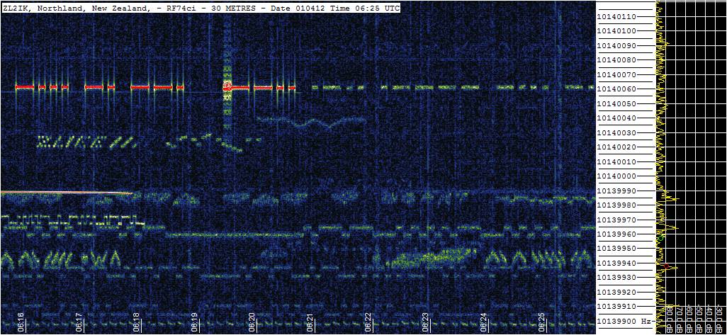
My Prop and PA can now be put back in service as a 30m QRSS, WSPE, and OPERA Beacon without, out-of-band concerns.

With restored faith in design, I can move on, and produce a proper PCB to replace the now acquitted PA circuit.

--

Tuesday, April 24, 2012

30m Low Pass Filter Results

Here are the measured results of the 30m Low Pass Filter (see previous post).

Here is the Propeller Output without a Low Pass Filter. The tall center signal is the Spectrum Analyser's LO, the Propeller 10.140MHz signal is to the right of the LO, and the negative images are seen on the left side. The third and fifth harmonics can be easily seen, odd harmonics are typical of a square wave output.

Without LP Filter
And, here is the Output with a Low Pass Filter

With LP Filter

Here is the Propeller and Low Pass Filter test configuration.

Prop and Low Pass Filter

--

Monday, April 23, 2012

More 30m Low Pass Filters

Today was again, Low Pass Filter Day.

I built three 30m Low Pass Filters to use with the Propeller as the Keyer and RF exciter. Previous filter builds included a DC blocking Cap to avoid DC loading the Prop, but a Low Pass Filter should not include elements that prevent Low Frequency signals to pass even if they are not wanted. DC blocking should come before the LP Filter on the Prop.

My previous built filter were a little flimsy, they were built on .031mil PCB material, components in line with the axes tended to crack and stop working. For these board, I used .064mil PCB material.

The circuit I am using was calculated via the CalculatorEdge online service (there may be other online calculators that would work as well, but this is the one that came up first in Google search).

The Calculator suggested the following, which became (=>) the available parts used.
  • Two Inductors 594.4nH => 680nH as hand wound (I could have been more precise here, but, . . .  :-)
  • Two End Caps  1086.5pF => 990pF (3 - 330pF)
  • Middle Cap 1416.1pF => 1320pF (4 - 330pF)
30m Low Pass Filter
I updated the circuit on my CircuitLabs Workspace, and ran some plots with the slightly different component values that I have available. The second harmonic rejection is reported as down -45db.

Down -45db at 20MHz
The results:
30m Low Pass Filters
I am going to use SMA connectors for all of my projects now, thanks to Jeff - KO7M I had enough connectors to complete two filers. More SMA Connectors and Jumpers Cables are on order.

One of the above Filters will be sent to a friend.

--

Monday, April 16, 2012

TCVCXO Six Hour Stats

In preperation for finish building Huff-n-Puff Circuit, and then running the Huff-n-Puff TCVCXO Spin Code on the Propeller, I have been running some Master Clock Frequency Stability and Accuracy data collection code in monitor mode and displaying the statics.

The displayed Frequency Error is computed as; the clock count form the desired 80M clocks, per 1 second pulse from a GPS. The percentage reflects; the direction, and magnitude of over a sample period. For this test the sample period is 6 hours.

Note: the resolution from the clock counter within the Propeller when compared to the GPS second pulse is 16Hz, this maybe a function of my particular GPS or the clock count function of the Prop. Regardless, the error is recorded as; ERROR/16.

After about 12 hours of data collection, the TCVCXO stats indicates about +6% X 16 cycles per 80M clock cycles, or an error of;

16 x .06 / 80M => 12 x 10^-9 
or, 12 parts per billion

The intent is to install the Huff-n-Puff circuit and then note the same stats.


Is this necessary?      No, . . but it is fun to see what frequency accuracy and stability can be obtained with simple hardware!  :-)

--

Friday, April 13, 2012

Prop - New Smoke Installed

I worked up the courage (and found time) to troubleshoot the Smoked Propeller Protoboard (see previous post).

Close microscope inspection, and then some Resistance and Voltage Tests revealed nothing unusual.

The only known casualty was the LCD. The last time I was working on the Prop, I must have plugged the LCD onto the Header incorrectly, I think I must have displaced it by one pin. The screen went half Black, and then a little Smoke was emitted (from somewhere)!

Another LCD was installed and now all is working as it should.

So, now back to the Huff-n-Puff experiments.


BTW, Anyone want a slightly used LCD, . .  cheap, without its magic Smoke contained? :-)

--

Wednesday, April 11, 2012

HomeBrew Prop-UI

While building my courage to troubleshoot the Smoke Released from my Propeller (see previous post) I have been designing a User Interface Board (UI) for the Prop. The idea is to avoid many of the point-to-point wire connections and provide as much of the user interface on one board.

The UI will be programmed to set: Transmit/Receive Frequency, CW Speed, Beacon Type/Timing, and a host of other function that have not been thought of yet. It is a general purpose UI for controlling the functions of the Prop. Note: Jeff and I have used the Prop for Beacon Transmit functions, but we have not successfully use it for a LO and BFO for a receiver yet (only due to lack of time and effort). There maybe concerns with phase noise, and Prop generated QRM, when used in a receive function.

The connection to the Prop Protoboard will be a single eight pin header.
  1. SCL (I2C)
  2. SDA (I2C)
  3. 5 Volts
  4. Ground
  5. Clock Interrupt
  6. Reset
  7. Sound
  8. Switch Interrupt 
Currently the board will contain:
  • LCD Display (A Parallel LCD but the board will provide the I2C converter)
  • LCD I2C (another connector for an alternate display from another manufacture)
  • Real Time Clock (RTC)
  • Battery Clip for RTC Backup
  • Eight LED's
  • Two Rotary Encoders with Push Buttons
  • Two Push Buttons
  • Piezo Speaker
  • 3.3Volt Regulator

Top Side - LCD
Back Side - Quad Pot, RTC, and Two I2C Expander
The knobs, Push Buttons and LED's are not shown in the 3D images ( I still need to build (or find) their 3D models).

The UI will fit on the Propeller USB Protoboard along with the Standard KeyBoard, Video Connector, and Mouse (KVM). The I2C expanders that are used on the Prop-UI will minimize the required I/O pins from the Prop, allowing the KVM to be used when desired.

Note: there are many Display Boards available on the Internet, but nothing that provides a low pin count connection to the Prop, which include the peripherals that I am including for the UI.

The UI board will be about 2.5 x 3.1 inches, which is much bigger that most of my projects.

If all goes well, this project will be sent to the PCB manufacture by Friday, then a two week wait for the first three boards to return.

--

Saturday, April 7, 2012

Propeller Project Magic Smoke

I have been playing with my Propeller TCVCXO Frequency Master Clock. I am attempting to build the Huff-n-Puff circuit as previously blogged. I have made good progress, the TCVCXO is very stable and easy to adjust.

Jeff and I wrote a simple SPIN program to compare a GPS 1Hz pulse to the 80M clock cycles of the processor. An off Frequency error shows up as a deviation form the desired 80MHz. A simple subtraction displays the difference.

But then, . . .

I was making a few wiring changes to the protoboard and applied power - An audible Snap, and a faint puff of magic smoke was expelled from under the board,  and then the LCD went half black. . . .

I broke it  :-(

Now to trouble shoot the problem, but it may take a few days to get some time around this Easter weekend.

For now, My Beacon is OFF-LINE.


An After Thought

Maybe it was just the first Puff, . . . from the Huff-n-Puff working circuit ?

nah, it was real smoke  :-)

--

Wednesday, April 4, 2012

Encouragement from DipTrace

As an addendum to my DipTrace Survival Guide, the following is my email exchange, which can be found on the DipTrace Yahoo Group List, at:


Note: As can be seen, plans are in progress to help make PCB layout easier.


Hello

After completing the schematic capture, and now on PCP layout, how can I avoid the edit mode changing to "Rat Line" mode?

My schematic is complete and do NOT need any Rat Line additions or deletions, but it seems that the default edit mode is "Add Rat Line", even though all I need is to move parts, add or modify traces to build the PCB layout.

Having the mode switch to "Add Rat Line", when a pad touched is very-VERY irritating. The default mode should default to the last that I set.

If the default edit mode could be fixed, I would be a happy camper!

Regards,
Eldon Brown


Hi Eldon,

If you want to move a component, move mouse pointer over the component and left click to select it. It is important, that component will be highlighted in green color. If you see red highlight, program will switch to "Rat Line" mode. It triggers automatically, but we plan to add separate button for switching in "Rat line" mode.

You can also disable editing net structure (Route/ Lock net structure) to prevent wrong connections.

Alex Mihailenko
DipTrace Team


Alex,

Thanks for the encouragement, but,. . .

I deal with very small, very high density boards where many components overlap, and multiple via's are often contained within a component outline. Clicking on a component without inadvertently selecting a pad is problematic (especially SMD's). And therefore, in my experience, changing into "Rat Line" mode happens VERY often, which requires YET another attempt to re-set the mode to do the task at hand (with many wasted mouse clicks).

Also, "via's" are the worst offender, trying to move a via is always unnecessarily difficult (there must be a better way that I am missing). Each time I click near a via, the mode switches to the unwanted to "Rat Line" mode. To move a via, I have "learned" to very carefully click on one of the four, very small "magic" spots around the via (at 3, 6, 9, and 12 o'clock positions). Otherwise the mode switches to the unwanted "Rat LIne" mode, again :-(

Note: as per you reply:

>> It is important, that component will be
>> highlighted in green color. If you see red highlight, program will switch
>> to "Rat Line" mode. It triggers automatically

Maybe if that logic was reversed all would be well.

Anything new, developments, quick fixes, updates, or training tips, to address this problem will be greatly appreciated by myself (and maybe others).

Thanks.

Regards,
Eldon Brown


-

Tuesday, April 3, 2012

TCVCXO Boards Received

Yesterday, I received my TCVCXO PCB back from DorkbotPDX (15 days). These will be used as a stable replacement for the Master Clock on the Propeller USB Protoboard (see several previous posts).


HB 10MHz TCVCXO Propeller Daughter Boards


With a little work two boards were; loaded and initially tested. Jeff - KO7M will receive the second board for his Prop.


Ready to Load Parts


The board size is a little over 0.4 x 0.4 inches, and is made for 0603 and 0805 components. This new board was created to plug into existing hole on the Propeller USB Protoboard.

And of course, More testing is yet to come (although the Homebrew prototype has been doing well, and has be used in my 30m Beacon for the last few weeks).


UPDATE
Jeff and I have used the TCVCXO sucessfully with our Protoboards, the only difficulty is I miss located the third (single) pin on the PCB, it is slightly left of the of its intend spot.  This mistake makes the board sit slightly crooked on the Protoboard. But, the hole-to-pin slop allows correction (while soldering) for most of the misalignment. The alignment will be corrected on the next boards.

--

Monday, April 2, 2012

Happy April Fools Day


OK, it was a spoof, . . . don't believe anything you read from me, or anyone else, on - April Fools Day.

Really, . . 415,448,837,209 miles / Watt ???   (see previous post)


Happy April Fools Day !  :-)


--

Sunday, April 1, 2012

QRP Tests For The Night - Spoof

As most of readers of this Blog know, I have been playing with low power 30m QRSS Beacons (10.139945MHz) for several years. The current typical configuration includes a 9 Volt battery, a Homebrew PCB with crystal oscillator, modulator and timing control. The output has been measured at 43nWatts on a pQRP calibrated RF Test Set. Due to to temperature variation, the frequency stability, and timing was always a bit of a problem.


30m Beacon - 9Volt Power - 43nW RF


Tonight for the first time, I connected one of the little Beacons up to my recently installed 300 foot Off Center Fed Dipole (OCFD), which is at 90' AGL (Above Ground Level ). I kept the 9Volt Battery as the power source, but connected the Propeller Microprocessor up to control the modulation and transmit timing control. Jeff - KO7M recently gave me some SMA connectors, which were used to connect the coax at the edge of the board. Thin jumper wires from the Propeller Microprocessor were soldered into the circuit to key the transmitter and control timing. Holding everything together was easy with the aid of Double Sided Tape.

The first contact was recorded on KK7CC Grabber in Las Vegas. The Slash Code CALL can be easily decode; forward slashes are "dots", and the backslashes are "dashes".

My CALL (WA0UWH) is seen as: "/\\ /\ \\\\\ //\ /\\ ////", followed by "- WA".

My Slash Code CALL as Recorded on KK7CC Grabber

Later in the evening, a weak signal was recorded in New Zealand on ZL2iK Grabber.

My Slash Code CALL as Recoreded on ZL3iK Grabber

Note: the faint delayed signal a few milliseconds later of the same data, it is probably the signal received via the long (reverse) path around the world at 17864.3 miles, the direct short path is only 6992.5 miles.

For specmanship, the long path is equivalent to:

43x10^-9 Watts / 17864.3 miles = 415,448,837,209 miles / Watt

OR, that is about

415,448,837,209 / 1AU / 2 = 2233.595 Trips to the SUN and back with only 1 Watt

I think my recently installed (and well tuned) Antenna (thanks to Jeff's Help) provided the Effective Radiated Power (ERP) necessary to achieve these results. The gain in the direction of New Zealand must be extraordinary. Perhaps the slight slope (and droop) of the Antenna wire in the direction of New Zealand aids the radiation angle necessary to achieve around the world ionosphere ducting. I will have to verify the Antenna's expected performance with EZNEC.

I should have time to repeat this tests and results sometime in the coming year, but for now, other projects will divert my attention from this type of extraordinary results and experiments.


UPDATE - Apr 2
OK, it was a spoof, . . . don't believe anything you read from me, or anyone else, on - April Fools Day.

Really, . . 415,448,837,209 miles / Watt ???

Happy April Fools Day !  :-)

(Actually, there are a few "facts" within the post)

--