Monday, January 30, 2012

Unode Biased Push-Pull FET

This is my new Homebrew "Vacuum Unode Biased Push-Pull FET Power Amp" of my own design.

Unode? - with the vacuum tube containing only one element, look closely, you will see, I did not know what else to call them :-)  And, I like the name and the glow.

I have experimented with this type of bias for FET Power Amplifiers before. Building some Amps with varying degree of success. The Unodes (lamps) are used as a Positive Temperature Coefficient (PTC) element providing a nice stable bias environment for power FET's.

Unode Biased FET Power Amp

This is the prototype, with Homebrew PCB being planned (and soon created). Performance measurements, Low Pass Filter, and other part modifications will most likely follow. For now the Amp is doing a smoke test. Power and Spectrum measurements will soon follow.

A real Toner Transfer PCB will eliminate the Grounding Solder Globs and make the amp much more presentable. Soldering over the edge of a Manhattan pad is always difficult. Next time I build this style of prototype board, I will use Solder Wick for the over-the-edge ground connections.

This power amp (in it's final form) will be used with my Propeller WSPR, QRSS, and OPERA Beacon.

--

QRSS Report

A new QRSS report, this time from Vince - N9VN near Chicago at 1676 miles, Thanks Vince.

QRSS Report
1676 Miles with 62mW's
That is my Propeller Graphic, SlashCode Call, and followed by "WA", as seen above the Flying W Graphic from W1BW.

--

Sunday, January 29, 2012

WSPR, QRSS and QPERA Beacon

I am have way too much fun with my multi-mode Propeller WSPR, QRSS and OPERA Beacon.

WOW, I Just got a Spot from Antarctica at 15,825km with my little 62mW Beacon !!

For specmanship, that is 157,328 miles per watt.

WSPR Spot with 62mW's
see: http://wsprnet.org/drupal/wsprnet/map
TimestampCallMHzSNRDriftGridPwrReporterRGridkmaz


2012-01-30 03:02  W5CGC  10.140234  -21  0  EM13ka  5  DP1POL  IB59uh  13407  157 
 2012-01-30 02:56  VE6PDQ/1  10.140161  -16  0  DO33fl  5  DP1POL  IB59uh  16025  147 
 2012-01-30 02:36  DJ6OM  10.140164  -21  0  JN58se  1  DP1POL  IB59uh  13314  187 
 2012-01-30 02:30  DL3KAV  10.140281  -26  0  JO30ms  0.5  DP1POL  IB59uh  13561  186 
 2012-01-30 02:30  K5XL  10.140252  -19  0  EM12kp  1  DP1POL  IB59uh  13369  158 
 2012-01-30 02:30  ON7BBR  10.140225  -23  0  JO21fh  1  DP1POL  IB59uh  13604  185 
 2012-01-30 02:30  C91PM  10.140244  -15  0  KG64ha  5  DP1POL  IB59uh  5599  196 
 2012-01-30 02:28  WA0UWH  10.140176  -21  -3  CN88xc  0.05  DP1POL  IB59uh  15825  150 
 2012-01-30 02:28  G0MJI  10.140185  -13  0  IO83ni  5  DP1POL  IB59uh  13800  182 
 2012-01-30 02:22  VA7SK  10.140205  -20  0  CN89lf  5  DP1POL  IB59uh  15970  150 
 2012-01-30 02:20  KF7O  10.140155  -25  -1  DN06tb  1  DP1POL  IB59uh  15492  152 

Each mode (WSPR, QRSS and OPERA) is transmitted once each 12 minutes.

My Propeller 30m WSPR, QRSS and QPERA Beacon Station

--

Saturday, January 21, 2012

OPERA Running on Ubuntu, It "sort of" Works

I have OPERA 1.1.6 . . .  "sort of" working on Ubuntu via Wine :-)

NOTE: The following has "Hung" the Ubuntu Gnome Display System, I had to ESC to command line to recover (ctrl-alt-F1), kill the OPERA process, and then return to the Desktop via F7.

CAUTION: Use at Your Own Risk

Two DLL's were needed; MSVBVM60.DLL and pdh.dll. I found them online, but was advised not to download from un-trusted sites.  I have a local XP system from which the files were found, and I copied them into the Ubuntu OPERA directory,

To make things easier, I change the default permission of the executable to "mode 755", with:

$ chmod 755 Oper*.exe

Then I ran the Install as:
$ wine ./Opera*Install*.exe

To run OPERA, execute:
$ wine ./Opera\ v1.1.6.exe

After adding my Operator Information and selected the sound card for input, the waterfall came alive with signals. The sound card was over driving the Decoder, but a quick adjustment to the Ubuntu Volume control fixed  that.

I was able to decode several signals on 10135mHz.

Sill known problems that I have not solved:

  1. The CPU Usage meter does not work.
  2. The CAT Rig control does not work for my FT-817, but Tones are created on the output as can be heard with a temporary speaker connected.
  3. Attempting to Set Configuration sometimes Hangs the Display System
Like most MS programs running under WINE, there will be a lot of WINE "fixme:" errors logged to the command line window form which OPERA was started, most can be ignored.

Maybe these problems will be solved by someone knowing much more than I.

--

Friday, January 20, 2012

Mackinac

Tess and I just survived 4.5 days without Power, Heat, and the Internet.

Without the Internet, I only had my paper "Sprat Magazines", "Radio-Frequency Electronics" book and few catalogs to read for entertainment. I will stock more printed material for next time.

Driveway
(the way out)
We are still snowed in (10 inches in a 300' driveway), but the power is back on, and the Hanger/Shop is warming up.

Life may soon return to normal.


Update: My friend Jeff - KO7M tells me I misspelled "Machinac" - OK, I am not a local :-)

--

Monday, January 16, 2012

Propeller Beacon Feld-Hell Font

The Propeller QRSS Beacon gets a Feld-Hell Font, the mode and font is known as Hellschreiber.

Check it out, on Jeff's Blog:


Soon, Hellschreiber mode will be added to my Propeller QRSS Beacon.

Note: Jeff created the font from scratch.

--

Sunday, January 15, 2012

Propeller Tests on WSPR

My friend, Jeff - KO7M, has been experimenting with WSPR on the Propeller. Check out his blog at:


We have been trading Propeller code segments for experimental Beacons. Due to his lack of a Low Pass filter, I do not think he has actually put it on an antenna yet, but he is working on a HB design. Soon I am sure on-air experiments will follow.

Jeff and I talked about how we could provide non integer frequency shifts as needed by WSPR, I suggested that maybe we could just use "1Hz" shift and let the proclaimed PLL Jitter do the rest. It looks like it has worked - now that's a hack!

Thanks Jeff, I will have to include WSPR into my current Propeller 30m Beacon, maybe after you completed your tests.

--

Saturday, January 14, 2012

Beacon Stacking via 10 Minute Sync

I received the following via Google+ and emails, it is archived here for myself and my blog readers.

---------------
From Peter Mulhare
Eldon

Just got in from Dinner........here is your first Stack pretty amazing, absolutely perfect copy from a stack of 6 images - 1 hours worth. I think you will be suitably impressed. Note that ZL1EE, W4HBK have also shown up stacked, also in there are G0MBA (@ '090), KC7VHS (@ '070), G0PKT (@ '980), and another station @ '925. These stations are not stacked because they are not running 10 minute frames.

Excellent result Eldon!

Pete
iK

Six Stacked Frames
Single Frame
--------------
From Eldon Brown
Peter,

Would you mind if I share your message and Initial Stacked Results on my blog? I have many readers that do not have Google+ and I want to Archive the results within the blog.

When we establish all is working as expected, I want to disconnect the Power Amp (62mW) and run directly from the Propeller with only 3mW. Your stacked images maybe be the only way to see the results.

Thanks Eldon - WA0UWH

-----------------
From Peter Mulhare
Hi Eldon

I don’t mind if you share the results, that’s fine by me. The best I’ve done at those kind of powers was to Western Australia, 5500 km to VK6JY, running 7mW from the output of my FEI 5680A Rubidium Frequency Standard, keyed FSK with an ATmega16 keyer I designed. I think we would need pretty good conditions to do it, but let’s give a shot!

The windows of opportunity at the moment are pretty short, limited to grey line propagation around one or other of our sunrises or sunsets, with the other one in darkness. I will have a play with DXAtlas, and see if I can come up with some dates to try.

Note that Bill W4HBK was in nearly all night on the Grabber, now that’s due to the way the grey line effects work between me and Florida. The problem with Washington is that you’re so far North and much closer to my Longitude, making us a north/south path, where to Florida the path is so much more east/west.

I’m impressed with the accuracy of your timing! the stacked signal has no thickening due to timing jitter, which is excellent, the computer clock here, is sync’d to the UTC second with several NZ University Caesium Beam controlled NTP servers, over the net. Software is Meinberg V4 Timeserver.

Pete
iK

-----------------

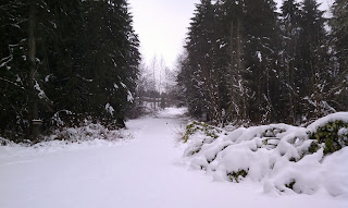
The First Snow - 2012

This is the First Snow of the year has just started, it is a good time to be inside with Ham Radio, and having fun coding my Propeller Beacon (see previous posts).

The First Snow - 2012
The photo was taken from my Loft (shack) window, with the 450 ohm Ladder Line in the foreground. The Ladder Line feeds a Off Center Fed (OCF) Dipole 90 feet above ground. So far the 30m 62.5mW Beacon and Antenna have received good reports from many remote locations. The beacon is transmitting both QRSS and OPERA on a 10 minute sync cycle.

A nice map of Generic OPERA reports are available at http://pskreporter.info/pskmap.html

--

Friday, January 13, 2012

Beacons in Sync

Propeller "Multi-COG" Programming is much simpler than I had imagined.

To date, I have used time delays to to pace my QRSS and OPERA Beacons, both running on same Propeller Micro Processor (using only one COG). The timing was typically just a 6 minute delay after the last transmitted data.

Peter and some other Grabber owners can Stack grabs to provide even more sensitive reports. A similar technique is used by Astronomers to photograph very faint stars. The typical QRSS Grabber is programmed to capture a frame each 10 minutes. To play the game, QRSS Beacons need to sync to a 10 minute interval, it does not matter where in time, but repeat in sync with itself.

So, this requirement provided me an opportunity to learn more Propeller Spin Programming. I tried several approaches to provide a Real Time Clock or Sync Timer Function, but nothing I programmed was working very well.  With more reading, learning, and experimenting, I decided to try to build a "Epoch" counter in a second COG.

It was so easy I could not believe it. To start a new COG, the following line is all that is needed within the first (default) COG:

cognew(procedureName, @someStackSpace)

The "cognew" statement specifies  the new COG's default starting procedure, in the same way as the default GOG (0) always starts with the first listed procedure in the Spin file.

The new COG has access to all of the routines, variable, and constants listed in Spin file. In my case, I need a "delay(1000)" routine to update the Epoch counter within the new COG.


PUB UpdateEpoch                 ' Runs In its own COG
    repeat
      delay(1000)
      Epoch++


Here is the First COG Code for "Main" that starts and uses the Epoch for Sync:


VAR
    Long RFFreq

    Long Epoch, EpochStack[16]

PUB Main | Sync

    doInitialize

    cognew(UpdateEpoch, @EpochStack)

    Sync := 60 * 10             '10 minutes
    Epoch := 0

    repeat

      RFFreq := Qrss_Tx_30m
      doQrssBeacon
      noTone
      delay(10000)

      RFFreq := Opera_Tx_30m
      doOperaBeacon
      noTone
      delay(10000)


      ' Delay for Sync
      repeat while Epoch // Sync
        delay(100)


Note: The "//" operator is modulus function.

The new and much improved (published) delay routine is:


PUB delay(ms)  | t

    t := cnt - 1088             ' 1088 is Published Time for Overhead at 80mHz
    repeat ms
       waitcnt(t += MS_001)


Now, my Beacons should now show up on the Grabbers in 10 minute Sync.

I am enjoying Programming the Propeller !


--

Tuesday, January 10, 2012

Propeller QRSS and OPERA Beacon

My Propeller 30m QRSS and OPERA Beacon Station

Currently I am running the Propeller; on QRSS at 10.140080mHz, and OPERA at 10.150380mHz, in single program time sequence order, with a 6 minute Receive-only delay between beacon transmit sections.


PUB Main

    doInitialize

    repeat

      RFFreq := Qrss_Tx_30m
      doQrssBeacon

      RFFreq := Opera_Tx_30m
      doOperaBeacon

      noTone
      delay(60000*6)


The time sequence is controlled via a single program, but eventually my goal is to simulcast, both QRSS and OPERA Beacons during the same Tx Window, leaving more time for Receive and reporting.

And, then I plan to add WSPR Tx to the mix :-)

With the 8 COG's (processors) of the Propeller, it should be all very do able. It is, . . .  just software!

I also want to provide for TX-Relay control or Receiver Power Control, as my poor Ensemble RX receiver (on another antenna) is currently having to swallow the near field 62.5mW's of the Propeller's After Burner, which is not good. Also, a TX-Relay would allow for TX and RX to use the same (my new higher) antenna.

As stated, I am currently only operating on 30m, but the Propeller can operate on any HF Band and I plan to do so. But a Band switched Low Pass Filter is necessary, I have one sketched on a napkin, but have not committed anything to a protoboard, yet.

Note: my custom "delay" routine had to be modified to accept large delay values. There maybe a better approach, but this works for now.


PUB delay(ms)
  repeat while ms > 10000
    waitcnt(cnt + clkfreq * 10)
    ms -= 10000
  waitcnt(cnt + clkfreq/1000 * ms)


UPDATE: I found a published "delay" routine, and now using it, see the next post.

I am just have fun with Beacons and the Prop.

--

Sunday, January 8, 2012

My Propeller On OPERA

My Propeller is now transmitting using "OPERA", and have received a few initial report, see Julian-G4ILO's blog. Thanks Julian.

More information is available at the Opera Yahoo group .

I plan to fold the QRSS and OPERA Code together into one Operating System with multi-Modes. For now I am running Julian's code with my CALL inserted. It took a while for me to figure out how to do that, and more details will follow.

My OPERA Reports in Red
OPERA is a little like "WSPR" but it was designed for the "CW" crowed, it is reported to work at weak signal levels than WSPR.

This operating mode from QRSS to OPERA was easy, because (most) everything is in software.

I think we need a few new term: "SDT" = Software Defined Transmitter, and "SDX" for Software Defined Transceiver.

Note: I am using the OPERA PC software (see above) just to receive my reports vis the Internet, the Propeller is doing the transmitting without the aid of the PC.

--

Saturday, January 7, 2012

New Antenna Measurements

My Off Center Fed (OCF) Dipole that Jeff - KO7M and I recently installed, had not been physically measured until today. The size of the elements were chosen to fit the available space, and the height was, what ever support was shot into the trees.

Today with some reasonable weather, measurements were taken.

  • The short end of the dipole is 23 feet long
  • The long end is about 300 feet long
  • The height at the feed point is 90 feet, the ends are a little higher.
  • The Antenna is strung East - West, with the long end West.
  • The Feed Line is 450 ohm Open Ladder Line

The antenna height was measured with a Cell Phone, that is, the "Level App" was used to sight the feed insulator, while moving away until the talking Phone App announced  "45 degrees". The distance along the ground (plus eye height) should be the same as the height of the insulator, it is 90 feet.

Judging from the recent received QRSS reports, I think the antenna is working very well. Thanks Jeff.

--

Propeller 30m QRSS Received in Tasmania

Another DX report for the Propeller 30m QRSS Beacon, it has been received by Edgar - SWL in Tasmania, at 8355 miles.

Faint Propeller Signal Upper 1/5th

The Current Data Format
as Received by my Local Grabber
The transmit path map:

8355 Miles

For specmanship, that is (8355 / .0625) = 133,680 miles / Watt :-)

--

Friday, January 6, 2012

Propeller 30m QRSS Received in New Zealand

Another report for the Propeller 30m QRSS Beacon, it has been received by Peter - ZL2IK in New Zealand, at 6992.5 miles. Peter incorrectly decode my CALL, but it was close.

 My Propeller 30m Beacon
Received In New Zealand

The transmit path map:

6992.5 Miles

For specmanship, that is (6992.5 miles / 62.5mW) = 111,880 miles / Watt :-)

--

Thursday, January 5, 2012

Propeller 30m QRSS Received in California

Another report for the Propeller 30m QRSS Beacon, it has been received by Mark - K6HX of the Brainwagon.com blog and can be seen on his Grabber.

My signal is shown about 1/3 down from the top,  the transmitted repeated pattern is above the white line (oops, all of the lines are white :-)

Beacon Signal Received
 at: http://qrss.info

700 Miles

The Propeller QRSS Beacon output at 62.5mW on 10,140060MHz, the current data format is:
  • CW ID at ~15WPM,
  • A Propeller Graphic,
  • My CALL in SlashCode (i.e,. "/\\ /\ \\\\\ //\ /\\ ////" ), where "/" is a dit, and "\" is a dah.
  • Followed by a WA Graphic

Of course, because the signal (and output format) is just software, it could change on a whim.

-

Tuesday, January 3, 2012

Propeller 30m Beacon Received in Pensacola FA

My Propeller 30m QRSS Beacon is being received by the W4HBK Grabber in Pensacola FA, about 2206 miles, with only 62.5mW.

I know that Watts/Mile are not real specs, but,  2206/.0625 = 35296 Miles / Watt

W4HBK QRSS Grabber

My SlashCode ID can be see upper left above the red line.

The transmit path map is shown below.

2206 Miles with 62.5mW
Note: other Grabbers are located around the world, an index or Compendium is provided by I2NDT.

--

Propeller 30m QRSS Signal Received in Las Vegas

With the help of a QRP After Burner (see previous post). That is: a power amplifier that boost my 3mW signal to a whopping 63.5mW, my Propeller 30m QRSS Beacon has been received 900 miles away by KK7CC Grabber in Las Vegas !!

KK7CC QRSS Grabber
My SlashCode ID is weak, but it can be seen and decoded above the red line.

The interactive grid map shows the path.

The Transmit Path

Here is the set up, Antenna Connection far left, Power Amp upper left, Low Pass Filter upper right, Propeller and Battery below. The PA is a simple un-tuned single IR-510 FET circuit, feeding a ~200 foot long Off Center Fed (OCF) Dipole at 60 feet high, strung East-West.

Update: The antenna was recently physical measure at 325 feet long and 90 feet high.

My Propeller 30m QRSS Beacon Station

--

Antenna Adjustments

Early this morning, without a rain drop in site, I decided to check the new Antenna that Jeff and I installed yesterday (see previous post). When installed, the feed point did not line up with the apex of the roof and therefore the Ladder Line could be wind blown and touch the metal roof. I can fix that by adjusting the support lines.

I knew I was temping fate and the performance of the antenna, by adjusting it in clear weather. The Great Antenna Gods would not like that.

Starting at the far end, I released about 20 feet of support line and retied it off. By the time I had the extra line coiled an secured, it started to sprinkle, and by the time I got to the other end to take up the slack, it was raining! The Great Antenna Gods have once again provided the inclement weather to ensure the performance of this new Antenna, Thanks :-)

Back in the Shack (loft) I noticed that I must have raised the feed point a little higher than before, the proper drip loop was gone. Another adjustment is necessary, but that will wait.

Also, when the weather clears, I will attempt to measure the height of the Antenna, a little trig should do the trick.

The Propeller 30m Beacon has been running on this new Antenna, but no reports so far.

--

Propeller 30m QRSS Spectrum

I had reluctantly attached my Propeller Beacon and new Low Pass Filter to an older 30m 1/4 wave vertical antenna near my Ham Shack. I know the Beacon output is very low power (3mW), but I did not know if the low pass filter was working as designed. I did not want my Beacon to disrupt others. But, it was attached, anyway.

Low Pass Filter
Yesterday, my friend Jeff - KO7M came over to help install a proper longwire/dipole antenna (see previous post), and I had plan to attached the Beacon to it. Jeff brought along his Spectrum Analyzer, so that we could take a look at the Propeller Beacon's output.

As expected, without the Low Pass Filter, the raw Propeller output fed into terminated 50 ohm load was full of trash and harmonics, which is VERY undesirable for a Amateur Radio Transmitter.

Raw Output
Without Low Pass Filter
After attaching the Low Pass Filter, the trash and harmonics were still there, but at much low levels, more than 40db lower, and unseen at the same scale. Now, I felt good about attaching the Beacon and Filter to the Newly Installed Longwire Antenna.

With Low Pass Filter Attached
The Single Spike Is the Fundamental Frequency
This is what a Transmitter Output should look like
Yet, when we looked at the spectrum via an open probe in the room, all of the trash and harmonics were still very much present.

Jeff got the idea that it was probably radiated from the processor itself. We wrapped the Propeller, Battery, and Low Pass Filter in insulating paper and then in aluminum foil attached to ground. Now, only the radiated power of the fundamental Frequency passing through the Low Pass Filter and leaking from the Ladder Line could be seen with an open probe. The open probe received signal was clean, the same as when the beacon was attached directly to the 50 ohm load at the Analyzer.

My Local View of My Beacon's Signal
My hope was to see my little 3mW Beacon on KK7CC's Grabber in Las Veges (900miles). But so far, no joy.

I have a previously built Homebrew Power Amplifier that I may try, it should boost the signal to 30mW, maybe enough to be received in Las Vegas.

My conclusion

I think the Propeller, with a Low Pass Filter, can be used for experiments with Amateur Radio Beacons. But as always, more experiments and data is needed to know how useful it will be. A report from a remote QRSS Grabber will help the investigation.

--

Monday, January 2, 2012

Antenna Installation Day

Today we had a great day of Amateur Radio.

My friend Jeff - KO7M came over to help install a new off-center-fed dipole antenna. Until now (since my move), I have suffered with just a 30m Vertical at 0' AGL for all of my Amateur Radio needs.

Today, was the day to fix that.

Jeff arrived about 10:00AM, the weather was clear with some overcast, we ware concerned that the Great Antenna Gods were not going to be pleased, with an installation that was not properly bathed with enough bad weather to obtain our desired performance. We went ahead with the installation regardless, with the idea we may have to settle for less than optimum performance. But the Gods smiled on us and provide enough showers to complete the installation with the required anointment.

We used my Tennis Ball Launcher (see previous post) to put a line into two tall fir trees, about 300 feet apart. With one shot at each end we had antenna support lines up maybe 60 feet, the actual height will be measured in clear weather. We had a lot of branched to snake the support lines around, but with two people the task was not too difficult, it just took time.

The desired feed line locations was about 50 feet from one end. So the counter poise was cut to exactly 23.50937 feet (plus or minus a few feet or so) as maybe needed for 30 meters. We do not know how well this plan will work, but it is what we have, and it fits the space available.

The long wire side of the dipole was cut to exactly, . . . where Jeff  stopped un-rolling wire, near the other tree, maybe 200 feet. The center insulator was installed, the long wire and counter poise were attached to the Ladder Line.

Pulling on the end lines took the antenna into the air, and into the near by tree branches and shrubs. With a little work, strong pulls and a small line over the antenna, the limbs were cleared. The antenna was now hanging is a big loop between the trees. A few more strong pulls and it was in place. The feed line location did not work out as expected, but the Gods were making it difficult to make further adjustments.  We picked up our tools and guide ropes, and headed inside as it was now raining.

Jeff had to make one more trip outside in the rain, because we needed to snaked the ladder line into the upper story loft window. Once inside the ladder Line rans across the room, attached to the overhead support beam and onto the radio station area. Later I plan to run coax to just out side the window and into a balun for a match.

By this time, we were glad we were inside, and out of the rain.

Inside and with a quick cut of the ladder line, a twist of the balun terminals on the Antenna Tuner, and the receiver came alive with strong signals being heard, . . . The Great Antenna Gods must have been pleased.

Now, I agree with the stories that I have heard, "All Good Antennas must be installed in foul weather, if you expect them to perform well"  :-)

A very Fun Day.

Now it was time to put my new Propeller QRSS Beacon on the air, and that as a continued report will follow.

--

Sunday, January 1, 2012

Propeller on 30m QRSS - SlashCode

The Propeller SlashCode modifications (see a previous post) to the Dots and Dashes routines was easy, similar modification was necessary to the end-of-character and end-of-word (space) routines. I also added the standard QRSS3 code.


PRI dot | i

  case CodeMode
    CW:
        sendTone(50)
        delay(100)
        noTone
        delay(100)
    QRSS3:
        sendTone(50+4)
        delay(1000*3)
        sendTone(50)
        delay(1000*3)
    SLASH_CODE3:
      repeat i from 0 to 4
         sendTone(50+1*i)
         delay((1000*3)/5)

PRI dash | i

  case CodeMode
    CW:
        sendTone(50)
        delay(300)
        noTone
        delay(300)
    QRSS3:
        sendTone(50+4)
        delay(1000*3*3)
        sendTone(50)
        delay(1000*3)
    SLASH_CODE3:
      repeat i from 4 to 0
         sendTone(50+1*i)
         delay((1000*3)/5)

Note: this Listing has been corrected (several times)

My Local Grabber - QRSS3
My Propeller 30m Beacon is in the center, the short burst of what appears to be trash before the first SlashCode is actually my CW ID at about 15 word per minute, followed by my ID again in SlashCode, and then WA as QRSS art follows (twice).

The stuff at the bottom is several other stations mashed together, for a better view of their signals goto KK7CC Grabber site. My 3mW signal, with a poor antenna, is maybe a little too weak to show up on KK7CC Grabber in Las Vegas (about 900 miles), but I will keep trying.

Propeller code seems easy to write, I am impressed. Note: I should have be using variables for the timing, but that is JASMOP (just a small matter of programming :-)

 --

Propeller on 30m QRSS - Output Power

First - Happy New Year to Everyone, I hope all is well, or as good as it can be.

Another first - this is my first electronic measurement of the year. Julian - G4ILO ask (via comments) "what is the output power" of the Propeller 30m QRSS and low pass filter circuit.?

I do not have a power meter that measures that low, but I measured 1.1V p-p across an accurate non-inductive 50 ohm load. With P=(Epp/2x.707)^2/R, the measure power is; (1.1÷2×.707)^2÷50 = 3mW.

Scale = .5v / Div
I still need to measure the harmonic content, my friend Jeff - KO7M has a Spectrum Analyzer that I will use to report the results.

But, looking at the ragged output waveform, I am becoming less hopeful that the Propeller will be useful for RF generation for radio work. The Propeller may be relegated to just control of other oscillators and/or displays.

Note: I would have expected more measured output voltage, because the Propeller is sourcing from an active 3.3V CMOS circuit. I need to investigate more.

--