Sunday, September 26, 2010

More QR Code

Here are just a "few" QR-Codes that I found via Google, they are apparently everywhere, if you know where to look.

http://www.google.com/images?hl=en&expIds=17259,17315,23628,23670,25834,26328,26569,26751,26762&sugexp=ldymls&tok=wJPNdc6pYq78MMGEUwH2Bw&xhr=t&q=qr+code&cp=2&um=1&ie=UTF-8&source=univ&ei=pSSgTOTxMZSisQOYrP3VAQ&sa=X&oi=image_result_group&ct=title&resnum=7&sqi=2&ved=0CFsQsAQwBg&biw=1059&bih=705

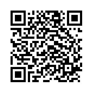
All of the above very long URL is contained in the following QR-Code image.
The Above URL

The reason that I started noticing QR-Codes, is because QR-Codes are the method of choice for sharing data; contacts, URLs, Apps, and more, between the Android Smart Phones. One phone displays the QR-Code, the second scans the first phone's display and decodes the results , effectively transferring information.

Using a "Bar Code App", any QR-Code can be decoded, regardless of  it size, location, and display device, assuming that it can be seen via phone camera. The image can be on a small stamp, or the side of a blimp - if it can be photographed, it can be decoded. Apparently, QR-Codes are used extensively in Japan, on everything from small products, to large Billboards and Neon signs.

If you have an Android Smart Phone, you too can easily read the above code and jump to the web page. Note; maybe other phones can do the same thing? For Android, see the app:


There is a Google Chrome Plugin that coverts any URL line to a QR-Code, which makes it easy to share an arbitrary page to a phone. Other online apps can be used to decode QR-Codes for any PC.

So, . . what does this have anything to do with Ham Radio? . . . Well, a lot, . . . as my new HTC Android Phone also contains several good Ham Radio Apps;  like EchoLink,  Exam Test Questions, APRS, CW Trainer, GPS Maping and a lot more. Oh, by the way, it can also receive and place phone calls  :-)  !!!


This mode of image communication may have a place in Ham Radio. Maybe a new form of QRSS or MEPT??


Update, yes it has now been done, See:


I plan on creating a QR-Code image for the back of my van, but so far, I have not thought of a good choice for content :-)

So, who will be the first to decode the secret word in the QR-Code of my previous post ???


Update


Link to some QR Code history (thanks to, Colin - G6AVK):


-- Home Page: https://WA0UWH.blogspot.com

Saturday, September 25, 2010

For The Geek in Me

For all of the Geeks - here is todays post:
As you can see by the time stamp below, I have been up, much too late.


UPDATE

I did not expect a QR-Code reply :-), but At 12:13AM, Jeff - KO7M, Replied with:


-

Thursday, September 16, 2010

In PIC Heaven

OK, I am now in PIC Heaven.

Long ago, I have used the Microchip 12C509 for many projects, but it is time to update.

In an attempt to find a PIC for some future projects, I ordered and received a few of the most popular.
  • Texas Instruments - MSP430 Launch Pad, Development and Evaluation Board = $4.30 with shipping at Mouser (how can they afford that!!!)
  • PJRC - Teensy USB Development Board - $18.00

Each Kit has a lot to offer; these are my initial reactions:
  • Microchip - has a lot of supporting chips and I think they have be around longer. Multiple programs to install and/or download. This should be easy, but I am have a hard time getting anything to work.  The Docs and Examples refers to different PIC than received?
  • ATmel Arduino - is VERY easy to program and it is quick to have something useful running. Just download one ZIP file and execute the main program.  The program contains links to read-only example files and a link to your project work space - very nice!
  • Solarbotics Ardweeny - is very small and the same ease of use as the Arduino and can be reduced to just the chip. A 6-pin programmer is needed, that is - a special USB to Serial Adapter (now on order).
  • Texas Instrument  MSP430 - Very inexpensive (evaluation board most function per $) - a little more difficult to program, but the chip has many built-in features, like on chip temperature. Two software packages are necessary to download and install; C and the Assembler. Demo code is a little difficult to find and set up - I will have to learn more.
  • PJRC Teensy - USB Development Board - It has onboard USB for programming and data transfer (I have this board on order)
Each of the above can be reduced to just an inexpensive PIC, for inclusion into a final project. Most PIC's are less than $2.00 - $3.00, availability, support (i.e., demo code), and easy-of-use (i.e., programming) will be the deciding factors.

I will update this post as I learn more.

.

Wednesday, September 8, 2010

Advancements DLP to PCB

It looks like there has been some major advancements for Mark's Direct Laser Printer (DLP) to PCB for homebrew hobbyist. See my previous posts.

Most experiments attempting to laser print directly onto PCB material evolves modifying the printer (cutting and removing parts) to straighten the paper (or PCB) path through the printer. Also, this normally requires the toner fuser to be removed, because it often contains slight "S" turns which is normally used to maximize heat transfer. Stiff PCB material will not pass through without modifications. A different method of image "affixing" is necessary.

In general; Jim KI6MZ's modification to the "carrier" makes for better image prints onto the PCB by grounding. As before the image is very fragile and require simi-melting in a 400 deg oven to affix the image before etching.

And now, Jim has also found a way to affix the image WITHOUT heat!

Jim suggests that the image can be affixed by placing the PCB with image in a container of Acetone Vapors for about two minutes. Removing it gently, air drying and it is ready for etch .

This sounds too good to be true, I am going to have to try this !!

Links to the details and thread are here.
I will report my progress using this method.

--

Tuesday, September 7, 2010

WinradHD Running on Ubuntu 10.04 via Wine

Until recently I had been listening to my Softrock RX Ensemble on my one-and-only Windows XP Desktop Computer, all of my other computers have been converted to Ubuntu Linux.

Today I found out that "WinradHD" I/Q Decoder will run via "Wine" on Ubuntu 10.04. I have Ubuntu on my HP Pavilion Laptop, which has a Stereo Mic Input Jack (a surprise to me). The Laptop decodes the SDR I/Q signals very nicely, with a very low noise floor.

My initial test configuration used two computers; one (window XP) to changed the Ensemble LO Frequency via a USB connection, and the second (the laptop) to run WinradHD and provide audio output.

Then, via the Internet, I found the "usbsoftrock" deamon for Linux, which is a kind of driver/program for the Si570. It is like a command-line version of a combination of  "USB Driver", "CFGSR", and "SRDLL" as used on Windows XP, and  as previously described. Usbsoftrock runs on Ubuntu along with WinradHD.

Usbsoftrock allows changes to the Si570 frequency via a command-line command on the Ubuntu Laptop, for example:
$ usbsoftrock set freq 10.140
Status can be listed via:
$ usbsoftrock status
I need to find the magic to control the Si570 via "usbsoftrock" directly from "WinradHD" on Ubuntu. Using the keyboard to set a Frequency is not exactly fun.


Note: A pre-compiled "usbsoftrock" Ubuntu package can be found as described on Steve Conklin, AI4QR web page and which was created by Jonathan, AF6YF (now N6JU) - Thanks Jonathan.

-

Friday, September 3, 2010

USB Mini-B Connector Received


Just received the USB Mini-B connectors (P/N 538-54819-0572) from Mouser. Hopefully sometime soon I will have time to modify the artwork to include this connector for my Marker/Beacon/CW project. See previous post.

Monday, August 30, 2010

Project Connectors - Old USB Standard

The world of USB Connectors has gotten a whole lot bigger, or smaller, depending on your prospective.

I need a connector for a new project that I am planning. The connector must be as small as possible as there is very little space on a 1 x 1.2 inch PCB.

  • On the PCB there will be; a stereo audio connector (for CW Keying), a push button switch, a crystal, and a 4 (or 5) pin connector which will occupy the majority of the space. The rest of the space will be used for; the Voltage Regulator and Decoupling Caps, 2N3904 RF Oscillator and Trimmer, PIC FSK Modulator, Status LED, Power Connector, and Antenna Connection. 
  • Most of the resistors will be of size 0603, and cap's will be 0804 mils, most traces will be 8/8 mils.
Proposed Project
  • The project is similar to my other 9 Volt Battery Frequency Markers, but this will be a smart QRSS Beacon. The required connector for; beacon mode, speed and message content programming. This thing will be used in stand-alone Beacon mode and casual interactive CW use.  My goals is to provide project documents so other, like minded people, can try their hand at this micro-circuit.
Why not make the PCB larger you ask?     Well, . . . I just like to make things as small as I can - just because I think I can.

The two connectors that I am considering using for this project are; the "Mini" or the "Micro" USB connectors. These are the smallest connectors that I have found. I know this will violate the "standards", by using them in this way, but it is my personal project and I will just have to not plug them into a standard USB fixture or cable.

In researching these connectors, I have learned a lot about the USB standards, and what that means for use with our smart phones and personal devices. A couple of things that I have learned are:
  • We have China to thank for requiring the "standard" "Micro" charger and data transfer connectors on our new cell phones (and personal devices), they said make the charger standard or do not try to sell it in China (Why couldn't we have done that?). And yes, the standard is the new smaller "Micro" connector and not the "Mini" connector that is currently found on our "slightly" older personal devices.
  • The first (and much larger) standard USB "A" and "B" connectors use four wires; +5 Volts, Gnd, +Data and -Data. The large flat "A" connector is normal found on the side of computers, and the smaller almost square "B" connector is normally used on peripherals. The connector establish the "Master/Slave" communication protocol.
USB A
Typically Found on Computers

USB B
Typically Found on Peripherals
  • Adapters cables with one large "A" connector are available for connection to a second small "Mini" and "Micro" connectors. These smaller connectors have five (5) pins for connection, the first four (4) are the same as the larger USB "A" and "B" connectors, on some hardware the fifth pin is shorted to ground to indicate which device is to be, "Master" or "Slave" ( I don't remember the details of which is which). Also, the standard requires that only one data connector is allowed on any new personal device (Note, a second connector is allowed, but it can only be used for additional power). UPDATE: the new pin was added at position number 4, old pin 4 became pin five, see the wikipedia doc.
USB - Mini AB
Previous Generation Standard

USB - Mini B
Previous Generation Standard
Note: the Corner Notches

  • The designators for these "Mini" and "Micro" connectors are "AB" and "B". The "AB" connector is rectangular and accepts both the "AB" and "B" male plugs, The "B" connector accepts the "B" plug and has corner notches as to reject the "AB" male plug.
  • The current China Standard is the "Micro" connector (below) for all new personal devices. It is similar to the "Mini" connector (above), but about 1/2 the size (unlike the included drawings would imply).
USB - Micro AB
Current Standard
USB - Micro B
Current Standard

The good news is; because the USB connector is not only for data transfer, it also used for device battery "charging", so we now have a "auto and home" charging standard for personal devices - we are no longer condemned to multiple charger-cord hell. Now we have one charging cord plug standard for all new personal devices. I have been told that many new cars now have USB charging connectors as standard equipment.

The Current Standard
A, B and Micro

What does this mean for my project; "Mini" cables and Connectors are available in surplus and new stock, and because they are no longer new, and now a deprecated standard,  . . .  so now - I am going to use them in my projects!

This HomeBrew project (and similar follow-on projects) will be used as an Transmit Exciter for the QRP HF PA as planned in a previous post.

I will provide more details as my Home Brew Project continues.


Note: For my future project reference, the Drawings and Photos were obtained from the Molex Catalog and Product Guides, at the following link:


The "Mini" and "Micro" USB connectors can be found on Mouser.com Catalog Page 1252

-

Friday, August 27, 2010

Ensemble - Config Info

This is my build adventures and recommendation for using the Softrock Ensemble SDR.

Note: my computer is an MS XP with SP3 - works for me details for other configurations may vary.

This is my best recollection of my build and test process, others can help by providing corrections, Thanks.

Note: not all Review Edits and Corrections have been made.

The following information is NOT anything new, it is just documented here for easy access.

In general, without any of the following software installed, the first time the Softrock Ensemble is plugged into the computer via the USB cable, it will request for a "new driver" and will ask where it should be found. This simple request for a "new driver" is good news - it means the computer has recognized new hardware. Note: only the USB cable is needed, the normal 12 Volt Power Cable, Antenna and Audio cables are not necessary for these initial LO tests.

Unplug the Softrock Ensemble from the Computer, so that is will wake up again for the following steps, after the initial programs are installed.

Links to programs and most of this information can be found in the Softrock Ensemble Build Instruction (down about 4 pages).

The following software is necessary:


USB Driver = A USB Driver for the onboard ATTiny85 CPU
  • Download the above ZIP'd file and de-compress it into a folder, you will need to know the path to the folder for the next step.
  • Re-plug in the Softrock Ensemble via the USB, it (as before) will request for "new driver" and where it should look to find it - supply the path to the above saved folder.
  • If all goes well, it will install and complete.
  • You should be able to un-plug and re-plug in the Softrock Ensemble with out errors or warning, you should hear the Standard MS Windows "ba-blink" or "ba-blonk" sound when plugging in or out.


CFGSR  = Configure Software Radio - Used to test Manual control of the Si570 Local Oscillator
SRDLL = Software Radio DLL - Used with CFGSR
  • Create a folder called CFGSR  some place, I suggest: C:\Program Files\CFGSR
  • Save above two downloads into this new folder, they must be in the same folder together.
  • I suggest: create a short-cut to the CFGSR.exe file for your Desktop, it will be handy for now and later testing.
  • Execute CFGSR.exe, the Si570 "control panel" will appear, which will allow you to set the Si570 Local Oscillator frequency, test as requested in the build instructions, Or, tune to a known radio frequency that you can monitor - you should hear the LO quite your receiver.
  • Follow the remaining build instructions -    . . .  You know, all of those dang filter toroids! - for the love of Ham Radio.
  • Note: after the initial testing of the Si570 Local Oscillator, these two programs will not normally be used. But they are good to keep around for trouble shooting.


WinradHD = A User Interface Program for Normal SDR Operation.
ExtIO_Si570.dll   = A Si570 IO DLL for programmatic control
  • Download and install "WinradHD"
  • Download and move the "ExtIO_Si570.dll" file into the "WinradHD" folder, normally found at C:\Program Files\Winradhd\
  • Note: a copy of this "ExtIO_Si570.dll" file may be needed in each of folders of any other SDR User Interface Programs that you may want to try.
  • Create a Short-cut link for the Desktop to the WinradHD.exe  program.
  • I suggest, right click on the link, edit properties add "-wv -as" to the execution line. The "-wv" allows WinradHD to be displayed in a normal (movable) Desktop window, and the "-as"  does an auto-start, see WinRadHD Home Page.
  • Note: you may need to select a "sound card" and the "Si570" IO from the WinradHD configuration controls.
Update: as of Dec 23, 2010 WinradHD changed name to HDSDR see: http://www.hdsdr.de/


Now, it is time for having some fun with SDR SWL.

-

Saturday, August 14, 2010

More, Fun With SDR

If you have followed my build of the Softrock Ensemble SDR Kit, you may want to re-review my previous posts - a lot of "updates" have been included as I have learn much more.

Thanks to ALL of the many e-mails, links, tips and tricks.

-

Friday, August 13, 2010

Fun With SDR

OK, so I am still new to Software Defined Radio (SDR) and the Softrock Ensemble Kit - I am still learning things that maybe I should have known? But, the following are things that I have found interesting:
  • On my PC I can run multiple copies of the I/Q Decoders and listen to multiple QSOs at the same time. I have room for three Decoders on the screen at the same time. I use; one to follow a conversation or net,  a second for waiting for a fading QSO to return, and the third to explore pop-up signals that I may want to listen to later. The only requirement is that the stations must be within 40kHz of each other, with a more expensive sound card that can be increased. Note: the multiple decoders can be all the same program, ran multiple times, or yet another program for other purposes. 
  • We all have had to listened to that annoying station just up the band from our intended QSO, and other than filters we could do nothing about it. With SDR you have very sharp built-in filters, and you can listen to multiple "selected" conversation at the same time - a new multi-tasking mode. Each Decoder can be set to mute (stop mode) if desired. I know, it sounds complex, but it is much more useful than you might think.
  • I checked the stability of the SDR, it is good enough for a QRSS Grabber. The ARGO Grabber program is just another I/Q decoder. The Ensemble is cheep enough that it could be dedicated to the task. I think it could also be used for Receive Only WSPR - more investigation needed.
More SDR to learn!

--