Sunday, March 30, 2014

A Measurement Fixture

While waiting for my replacement order of Toner Transfer Paper, so that I can continue my Minimal Project, I used some small cut-up scraps for this (another) project.

I have always wanted to build a self calibrating Fixture for my AIM-4170B Analyzer.

Self calibration means to me, that the "Short", "Open" and "50 Ohm Load", which are necessary for calibration, are a part of the fixture.  The "Open" is easy, just remove any parts from the fixture. The "Short" will be a simple push button switch across the analyzer terminals. And, a "Load" is another push button switch in series with a 50 Ohm resistor.

This approach to calibration is NOT exact, but it is good enough for most measurement that I do. For exact calibration, I have three certified (screw on) connectors that can be used.

The fixture as planned is only about 1.4 square inches and provides and SMA connection to an adapter on the AIM-4170B.

SMD parts can be scanned by placing them across the void on the fixture, and a plastic clip can be used to provide clamping pressure as necessary.

Parts with "Leads" can be pushed into the header shown in the center. There are three Ground header-pins, two groups of two header-pins are only shorted together and can be used to string leaded part together for a simple network measurement. And, there is one header-pin (center) that is connected to the analyzer.

Toner Transfer Method was used to build the fixture. As can be seen, only a small scrap of Transfer Paper was needed.


And, a small scrap of PCB material was used, which will be trimmed a little before going into the etch.


For etching, I use Ferric Chloride in a Ziploc Bag while kneading and running hot water over the bag. Only about 1 oz of Ferric Chloride is used.

In the Etch Bag
Almost Finished,
Some Copper (lower center) is Still to be Dissolved,
After cleanup, solder wiped, with switches and header attached, the fixture is ready to be attached to the AIM-4170B Analyzer.

The Analyzer Calibration can be done with the two switches. the upper push button switch connects two 100 Ohm Resistors in parallel across the analyzer terminals. The lower switch "Shorts" the analyzer terminal to ground.

The tapered section (lower center) is where SMD parts can be attached across either of the two voids.  Parts with leads can be plugged into the header.

The Fixture
The Fixture is installed, calibrated and ready for measurements.

Fixture Installed on the AIM-4170B
This fixture will help make sorting and matching Crystals that much easier the next time I build a Crystal Filter.

--

Oso Mudslide

In memory of the Oso Mudslide Victims - May you Rest In Peace.

The Mudslide near Oso Washington State is near my home (within 20 miles), I have spent many hours travelling the roads around Oso. I do not know any of the victims, but they are part of our Pacific Northwest Family.

(AP Photo/seattlepi.com, Joshua Trujillo)
For more photos and the full story, see: http://goo.gl/mpDsXl

There is no better place on a Hot Summer Day than in the local Mountains around Oso, running QRP, or down-on the river fishing and playing ball with Tess (my dog).

The mudslide came from a hill; across the River, across the Rail-Road Tracks, blocking the major local highway on the near side, and destroyed lives and homes along its path.

--

Saturday, March 29, 2014

Minima - AUDIO Board - Work In Progress

The SMD Caps were received, and therefore layout of my Minima AUDIO and Power Board has resumed.

This initial layout still has a few problems, and it has far too many vias (32) to my liking. I can build vias using the Homebrew Toner Transfer Method, but they are not fun, or at least at the size (40x15 mil) that I want.

This board contains (left to right, top to bottom): On the top row; TxRx Relay and Control, SideTone/CW, Audo PreAmp, Main Power Connector and Regulator (a little lower). On the next row; the KEY Jack, PTT Jack and Mic Amplifier, and the Audio Amplifier and Phone Jack.

My Minima AUDIO and Power Board
Proposed Configuration
If all goes well, the board size will be as shown at 2 x 4 inch. There is still room for additions or modification, but any additions will more than likely mean more vias. :-(

The circuit is a slight modification of the original Farhan Minima Transceiver circuit, I added; the Power Supply with Headers for the other Modules, I included the KEY and PTT circuits on this board because I wanted their Jacks near the Mic and Phone Jacks on the same board. A CPU signal and its Power Header is also included.

I still have to find a suitable Large Cap (500uF - Lower Right), I think the footprint as shown will work.

I just checked, and I need to order more Toner Transfer Paper, I may not have enough to build this board, especially if I make a mistake, Dang !


UPDATE: Mar 29, 2014 12:16

With a little digging, I found a stash of nice 35V 330uF Caps in my part bins, two of which I will use to replace the single 500uF cap as per the original schematic. The caps that I found are stand-up through-hole mount. I moved the connecting traces to the back side so that they could be soldered without the need for front-side solder (underneath the cap).

-- Please: Rate, Share, Comment and Subscribe.

Tuesday, March 25, 2014

Minima Caps on Order

I have been a little lazy lately, I have not been working on the Audio Module for my experimental Minima Transceiver (see previous posts). This is due to the lack of small large-value (47uF at 16v) capacitor in my part bins and junk box. Actually, I have many capacitor with the right values, but they are much bigger (physically) than I want for my Minima Modules.

Without having the small size capacitors in hand, it is difficult to layout the PCB and know for sure that it will all fit. So, the Audio Module layout is on hold waiting parts from Mouser.

For the required 47uF caps, I ordered the following two sizes.

The larger SMD "can style" caps are 50V. These will be usable in almost any of my future project. They are cheap, I ordered 150 just to make the postage worth while.

47uF 50V 6.3x7.7 SMD at $0.10 each - http://goo.gl/zpJaPP

 The smaller 1210 SMD non-polarized caps will be used where only 16V will be enough and space is limited. They are not so cheap, at about 8 time the cost of the above caps.

47uF 16V 1210 SMD at $0.85 each - http://goo.gl/4UWwCp

I already have on hand the other SMS large-value caps (i.e., <20uF) as required by the Minima.

And. . . .

The required Minima VFO - Si570 is on order from Digi-Key, at a price ($13.11 each) which is much less than I expected - http://goo.gl/bjOMPp

And, . . .

As an additional Minima Experiment, I orders the following two inexpensive parts.

Si5351 Clock Generator - http://goo.gl/DcZVaB
and its required crystal - http://goo.gl/WHxn2C

My intent is to try to use two of the outputs form the Si5351A for the VFO and the BFO. As I suggested on the Minima Refector, and yes, phase noise may be a problem, but this is just an experiment. More info to follow.


--

Sunday, March 23, 2014

Ham License Renewal

It has been ten years since I have dealt with the FCC regarding my Amateur Radio License. And therefore I am due for renewal.

I have received a few notices or reminders; one reminder from the AMATEUR RADIO SERVICE - THE W5YI VEC, INC., and another from the ARRL. I assume each provides good service for the few dollars they require in fees.

But, . . . it is easy to Renew with the FCC online, and it is Free, assuming you have (or can find) the correct web site for the FCC Renewal process. It is known as the FCC Universal Licensing System (ULS) at http://wireless.fcc.gov/uls.

The process requires login Registration, and then "ONLINE FILING" with login and password.

Renewal is accomplished by answering a few questions and check boxes, and then by submitting an Electronic Signature (typing your name into the space provided).

Its DONE !

With NO fees or hassles, which surprised me ! -  Thanks ULS

Now I am waiting for conformation and/or my renewed license in the post mail. I will then be licensed until 2024 !


UPDATE: Mar 29, 2014
Renewed - FCC Amateur Radio License Received.

--

Friday, March 21, 2014

SMAs Received

I finally received my SMA Connectors (Bling) from China, they seemed to have taken an extraordinarily long time in the postage. Actually, I think it was just my anticipation.

Now I can continue "plumbing" my project (see previous posts) by connecting the current Minima's Modules together. This is just an experimental Transceiver and therefore a layout like this will be acceptable for my use on the test bench. The connected layout is similar to that of the schematic.
Modules Built So Far
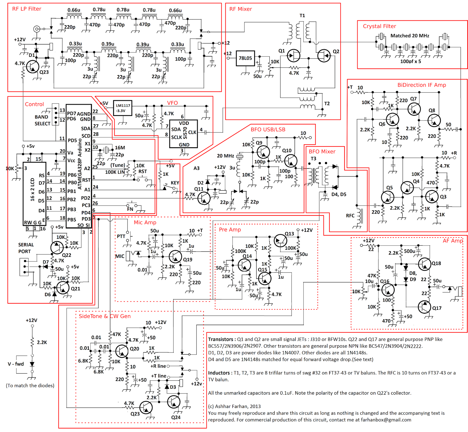
Farhan's Minima
Transceiver Schematic
There are four additional boards to be built; the RF Low Pass Filter, the VCO, the Micro Controller and Display, and the Audio Board.

The Audio Board will contain four of the schematic's named modules and power supply. My plan is to use the Audio Board and its power supply to provide power for all of the other modules via twisted wire and connectors.

The Audio Board Schematic has been captured in DipTrace, but the Layout is not complete.

More to follow, . . .


-- Please: Rate, Share, Comment, and Subscribe

Friday, March 14, 2014

Minima Modules

My Experimental Minima Transceiver Project is coming along.

Here are the modules (outlined in red) that I have built, or plan to build. Farhan's Mimima original schematic can be found here.

Minima Transceiver Modules
The dotted line modules contained within the large irregular red box at the bottom will be built on a single AUDIO board. This board will also contain the Supply, Voltage Regulators, and Header for connection to the other modules.

Click on Image to enlarge, the Right Click on Image to Open in a new Tab, then Left Click to expand to full size, then save if you like.


-- Please: Rate, Share, Comment, and Subscribe.

Thursday, March 13, 2014

Minima - BFO Module

I have finished constructing the Farhan Minima Transceiver BFO Oscillator Module for my Transceiver Experiments.

I used the same Toner Transfer Method that I have used for all of my other modules. The PCB is double sided, with oscillator power connection and ground plane on the backside. The size of this module is 1.0x1.5 inches.

Mimima - 20MHz BFO
This module supplies 20MHz to the Transceiver's BFO Mixer (via SMA connector on right) with frequency off sets for Upper Sideband (USB) and Lower Sideband (LSB). The Relay selects one of the two Sidebands via one of the two adjustment Trimmer Caps used with the oscillator.

On the initial power-up, the measured output was about 800mV PP (will this be enough?).

My circuit is slightly modified version of Farhan's published circuit, I wanted to use the colpitts oscillator and adjustment strategy that I have used in many of my other projects. I have kept the circuit's interface the same to maintain compatibility with Farhan's Minima Transceiver circuit.

The upper left pin header is for power (12v). The lower left header selects the Sideband, the extra (upper) pin in this header provides a quick way to select the Sideband with just a simple jumper, which will be useful while testing this module as a stand alone circuit. The white block in the center left is the Relay with its control circuit far center left. The BFO colpitts oscillator and output transistor are center right. The crystal (of course) is lower right. A red power-applied LED is upper left.

Note: I use EB2-3NU 3Volt Relays in most of my projects, and therefore when they are used in 12Volt circuits a limiting resistor is needed.

So now, after doing a little head scratching, my questions are:

  • What should the actual BFO Frequencies be for generating USB and LSB with a 20MHz IF?
  • Or at least, What is the expected difference between the two Frequencies?
  • Does this all depend on the width of the Crystal Filter?
  • In normal Transceiver operations, does the VFO Frequency also have to change (a little) when selecting the opposite Sideband?

More research about Superheterodyne Receivers on my part is necessary (and I thought I knew this stuff :-).

Any feed back via comments would be appreciated.

-- Please: Rate, Share, Comment and Subscribe.

Monday, March 10, 2014

Minima Bidirectional IF Amplifier

I had some time today to work on my Farhan's Minima Transceiver Bidirectional IF Amplifier Module as previously posted for the layout and design.

Because of the density and the desire to put as much ground plane on both sides of the PCB, I decided to layout the Input, Output and Power traces on the back side, which meant that via's would be necessary. Normally I avoid double sided Homebrew PCB, but sometimes they are necessary. The via's are 40 mil pads with 12 mil holes.

Homebrew PCB via's are not fun to drill or install at this scale, there are ten via's which were the last thing that I installed.

As with all of my Experimental Minima Modules, this module was created with the Homebrew PCB Toner Transfer Method on .032 board material with 1/2 oz copper clad.

Minima's Bidirectional IF Amplifier
0.8 x 1.4 Inche PCB
The upper string of components are used for Transmit (signal flow is left to right), and the lower components are for Receive (signal flow is right to left), which for simplicity sake, is the same orientation as the schematic.

The Backside
The Backside clearly shows the 10 vias that were necessary for the circuit layout. Maybe it could have been a single sided board, but the front side copper pour (ground plane) would have been broken into islands with poor conductivity between major sections and the SMA connectors. The vias are 40 mil pads with 15 mil holes. Small wire-wrap wire was used to make the via connections.

The circuit powers up, and amplifies a 20MHz low level signal in both direction depending on the power connection. Actual performance numbers will be measured later in conjunction with the rest of my Minima Test Modules. According to chatter on the Minima Reflector, the gain of this stage is not anything great, but I do not remember it's expected gain.

The power connector center pin is ground, therefore moving a two pin power connector is all that is necessary to change direction for testing

-- Please: Rate, Share, Comment and Subscribe.

Wednesday, March 5, 2014

New Cores for the RF MIxer

After building my Farhan Minima RF Mixer, and before taking it to Jack's LAB for performance evaluation, I replaced the two large cores with much smaller BN-43-2402 binocular cores. I had originally planned to use the smaller cores but I could not find my roll of very small wire with which to wind them, and therefor the first configuration sported the larger cores wound with 22 AWG wire-wrap wire. The RF Mixer worked, but . . .

Old Large BN-43-302 Cores
The new smaller cores fit the board much better, and they have also worked well on my BFO SSB Modulator/Detector board as well.

New Small BN-43-2402 Cores
as Original Planned
The small cores with the small wire are more difficult to wind, but with patience it can be done. The circuit requires eight turns of trifilar wire. With the small wire that I have (I do not know the gauge) only eight trifilar turns will fit (the circuit requirements are met).

One neat trick that I learned (in the distant past); before winding a DIY bifilar or trifilar wire together, stain one (or more) full length wires with colored Marks-a-Lot pen(s). The enameled magnetic wire takes stain reasonable well. A large felt tip pen and a slightly stretched (taught) wire makes the task easy. After twisting the wires and winding the cores, the stain will help make end identification much easier.

If I remember correctly, pre-stained filer wire is available for purchase, but I like DIY colored stained trifilar wire, because I can use any gauge of wire that I have available.


UPDATE
Based on the online Toroid Calculator, I may have only needed 4 turns on the BN-43-2402 Binocular Cores.

UPDATE
I had previously mis-published the part number of the Binocular Cores that I am using, the number and links have been corrected.


-- Please: Rate, Share, Comment and Subscribe.